Magnetoelectric velocity transducer with self-checking function

A speed sensor, magnetoelectric technology, applied in the direction of speed/acceleration/shock measurement, instrument, testing/calibration of speed/acceleration/shock measurement equipment, etc. Normal, speed sensor use, inconvenient detection, unfavorable failure prevention and other problems, to achieve the effect of mass production, compact structure, and modular design

Inactive Publication Date: 2014-06-25
NINGBO CRRC TIMES TRANSDUCER TECH CO LTD
View PDF4 Cites 10 Cited by
  • Summary
  • Abstract
  • Description
  • Claims
  • Application Information

AI Technical Summary

Problems solved by technology

[0003] Existing magnetoelectric speed sensors generally only have a speed measurement function. Before a locomotive equipped with a speed sensor is running, it is impossible to detect whether the speed sensor speed measurement function and the locomotive speed detection signal chain are normal. After the failure rate, and after the speed sensor has been used for a period of time, if you want to check whether the speed measurement function is normal, in general, send the speed sensor back to the original factory or the measurement and testing center, and install it on the corresponding test bench for functional testing. It causes great inconvenience to the use and detection of the speed sensor

Method used


Image

  • Magnetoelectric velocity transducer with self-checking function
  • Magnetoelectric velocity transducer with self-checking function
  • Magnetoelectric velocity transducer with self-checking function

Examples


Embodiment 1

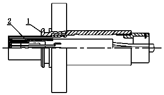
[0025] Such as figure 2 The magnetoelectric speed sensor with self-checking function shown includes a casing 1 and an inner core assembly 2 placed inside the casing 1 .

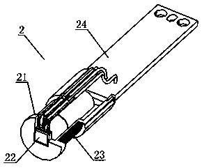
[0026] The structure of inner core assembly 2 is as image 3 , Figure 4 As shown, the inner core assembly 2 includes a connecting bracket 21, a Hall element 22, a coil 23, a circuit board 24, a magnetic steel 25, an iron core 26 and connecting lines.

[0027] The connecting bracket 21 is composed of three sections. The three sections are the induction element mounting base 211, the cylindrical coil frame 212, and the cylindrical mounting bracket 213. The connecting bracket 21 is made in one piece. There is a mounting groove on the sensing element mounting base 211, and the Hall element 22 is embedded in the mounting groove, so as to facilitate and accurately locate the installation position of the Hall element 22 and ensure the overall sensing distance of the product; The inside of the skeleton 212 is a ...

Embodiment 2

[0037] The Hall element 22 in the first embodiment is replaced by a sensitive element based on the magnetoresistance effect, and other structures and principles are the same as those in the first embodiment. When measuring speed, the sensitive element based on the magnetoresistance effect can sense the change of the magnetic field caused by the rotation of the gear, and output a square wave signal related to the gear speed through signal processing; The alternating magnetic field generated by the functional module outputs a square wave signal through signal processing.

Embodiment 3

[0039] A Hall speed sensor with a self-checking function, using a Hall element integrated with a magnet to replace the Hall element 22 in the first embodiment, the integrated magnet can replace the magnet 25 in the first embodiment, the integrated magnet The permanent magnet provides a magnetic field for speed measurement, so the magnetic steel 25 in the inner core assembly 2 of the first embodiment can be omitted, and other structures and principles are the same as those of the first embodiment.


PUM


Abstract

The invention discloses a magnetoelectric velocity transducer with a self-checking function. The magnetoelectric velocity transducer comprises an inner core component arranged inside an outer shell, the inner core component comprises a connecting support, an induction element, coils, a permanent magnet and a circuit board, the induction element is fixed to the front portion of the connecting support, the coils are fixed to the periphery of the middle segment of the connecting support, the permanent magnet is arranged in an inner cavity of the connecting support, the circuit board is fixed to the rear portion of the connecting support, a signal processing circuit and a power source circuit are integrated in the circuit board, the induction element and the coils are respectively and electrically connected with the circuit board, and after the induction element inducts magnetic field changes generated after the coils are powered on, processing is carried out by the circuits integrated in the circuit board to output square signals. Whether the function of the transducer and a detection signal link are normal or not can be detected by the transducer without dismounting the transducer, the operation is easy and convenient, and the structure is compact.

Description

technical field [0001] The invention relates to a magnetoelectric speed sensor. Background technique [0002] Magnetoelectric speed sensors generally include inductive elements, permanent magnets, power supplies, signal processing circuits, sensor housing components, etc. The principle of speed measurement is as follows: figure 1 As shown, the magnetic steel or other permanent magnets in the sensor housing generate a magnetic field, and an inductive element is set in the magnetic field. The speed-measuring gear is a magnetically conductive material with magnetic permeability. During the rotation of the gear, the gear teeth and tooth grooves of the gear approach the sensor alternately. The inductive element in the sensor causes the magnetic field strength around the inductive element to change alternately, the inductive element senses the change in the magnetic field, and the signal processing circuit processes the magnetic field change signal sensed by the inductive element,...

Claims


Application Information

Patent Timeline
Patent Type & Authority Applications(China)
IPC IPC(8): G01P3/48G01P21/02
Inventor 杨敏叶明盛陈增贤张燕亮王飞倪大成
Owner NINGBO CRRC TIMES TRANSDUCER TECH CO LTD
Why Eureka
Try Eureka