
Teaching-free laser three-dimensional measurement method and equipment based on reverse engineering technology

A reverse engineering, laser three-dimensional technology, applied in program control, instrument, computer control and other directions, can solve the problems of difficult and accurate control, accuracy cannot be effectively guaranteed, time-consuming and labor-intensive, etc., to improve processing efficiency, save time and measure cost, reduce Effects of technical requirements

Active Publication Date: 2017-06-20
HARBIN INST OF TECH
View PDF8 Cites 0 Cited by
  • Summary
  • Abstract
  • Description
  • Claims
  • Application Information

AI Technical Summary

Problems solved by technology

[0002] The original teaching and recording process of the five-axis linkage laser cutting machine is completed by the operator's vision and manual jogging. control; at the same time, due to the limitation of the probe structure, the accuracy cannot be effectively guaranteed

Method used


Image

  • Teaching-free laser three-dimensional measurement method and equipment based on reverse engineering technology
  • Teaching-free laser three-dimensional measurement method and equipment based on reverse engineering technology

Examples


Embodiment 1

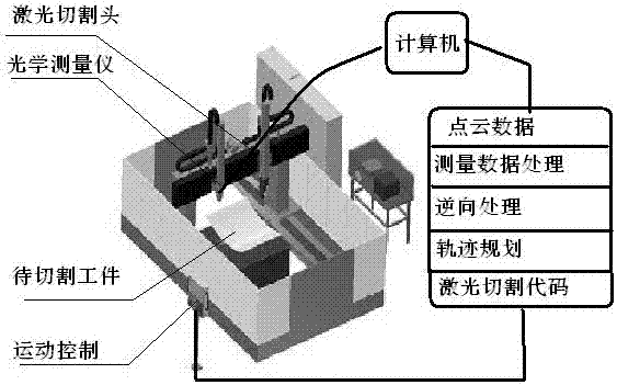
[0018] A teaching-free laser automatic cutting device based on reverse engineering technology, its composition includes: a five-axis linkage laser cutting machine, the five-axis linkage laser cutting machine is connected to digital acquisition hardware and a computer, and together constitute a three-dimensional system for obtaining point cloud data of the workpiece As for the measurement system, the optical measuring instrument of the digital acquisition hardware is fixed with the laser cutting head as a measuring device for the spatial point coordinates of the workpiece.

Embodiment 2

[0020] A teaching-free laser three-dimensional measurement method based on reverse engineering technology. An optical measuring instrument is fixed on the laser cutting head, and the motion control system of the cutting machine drives the optical measuring instrument to move together. The optical measuring instrument and the five-axis linkage laser cutting are used. The numerical control system of the machine constitutes an opportunity measurement system to complete the measurement of the coordinates of the workpiece space point, obtain its point cloud data, and then use the reverse engineering software to reconstruct the CAD model of the workpiece, and then realize the laser cutting attitude and trajectory according to the CAD model. Online planning.

Embodiment 3

[0022] In the teaching-free laser three-dimensional measurement method based on reverse engineering technology described in Example 2, the optical measuring instrument and the laser cutting head are fixed together, and the numerical control system of the five-axis linkage laser cutting machine is used to form an opportunity measurement system. It is completed on the same equipment, and the workpiece is measured and processed in one clamping, eliminating the error of secondary clamping.


PUM


Abstract

The invention provides a demonstration-free laser three-dimensional measurement method based on a reverse engineering technology and a device. A five-shaft linkage laser cutting machine usually needs one demonstration process before cutting, but original demonstration recording and returning process waste time and labor and is not easily and accurately controlled. An optical instrument is fixed on a laser cutting head, a motion control system of the cutting machine drives the optical instrument to move, and the optical instrument and a numerical control system of the five-shaft linkage laser cutting machine are utilized to form a borrowed-machine measuring system for finishing measurement of spatial point coordinates and obtaining point cloud data, then reverse engineering software is utilized to re-establish a CAD model of a workpiece, and further online planning on laser cutting postures and tracks is achieved according to the CAD model. The demonstration-free laser three-dimensional measurement method based on the reverse engineering technology and the device are used for online cutting of thin-wall and easily-deforming workpeices including large three-dimensional covering parts.

Description

technical field [0001] The invention relates to a method and equipment for realizing teaching-free laser cutting of complex plates by installing a measuring device on a five-axis linkage laser cutting machine and reconstructing its CAD model through reverse engineering software. Background technique [0002] The original teaching and recording process of the five-axis linkage laser cutting machine is completed by the operator's vision and manual jogging. control; at the same time, due to the limitation of the probe structure, the accuracy cannot be effectively guaranteed. How to make full use of existing system equipment to realize teaching-free cutting has become a practical engineering problem that needs to be solved urgently. Contents of the invention [0003] The purpose of the present invention is to provide a teaching-free laser three-dimensional measurement method and equipment based on reverse engineering technology. By using the optical measuring instrument and t...

Claims


Application Information

Patent Timeline
Patent Type & Authority Patents(China)
IPC IPC(8): G05B19/4097
Inventor 王懋露张宏志王扬刘俊岩杨立军
Owner HARBIN INST OF TECH
Learn More