
Wireless conference system

A wireless conference and wireless data technology, which is applied in transmission systems, digital transmission systems, and devices that provide special services in branch offices. Ensure work efficiency and avoid the effect of unreasonable role assignment

Active Publication Date: 2014-06-25
方图智能(深圳)科技集团股份有限公司
View PDF3 Cites 3 Cited by
  • Summary
  • Abstract
  • Description
  • Claims
  • Application Information

AI Technical Summary

Problems solved by technology

The host of this kind of wireless conference system realizes the reception and transmission of the conference unit signal through an external or built-in wireless receiver and transmitter, and only one receiving and transmitting circuit is placed in each unit, so it must face several problems : First, the power of the power supply battery is fixed, and the use time of each charge of the battery is limited. Due to the difference in the frequency and duration of speeches in the venue, some conference units in the venue will quickly run out of power, such as the speaker The power of the guests will be exhausted soon, while other conference units still have a lot of power that is not used; second, the wireless transceiver module of the conference unit needs to have a higher transmission power, and the wireless receiving distance of the conference unit is limited. The distance directly affects the application range of the conference unit, so the farther the wireless transmission distance is, the better. In order to increase the transmission distance and signal strength, the power consumption of the circuit will be increased, and the use time of each charging power will be shortened; Three, for the occasions where many conference units are used, the frequency band of the wireless signal is limited, and each conference unit occupies a frequency band, which is wasteful and limits the number of conference units used

Method used


Image

  • Wireless conference system
  • Wireless conference system
  • Wireless conference system

Examples


Embodiment 1

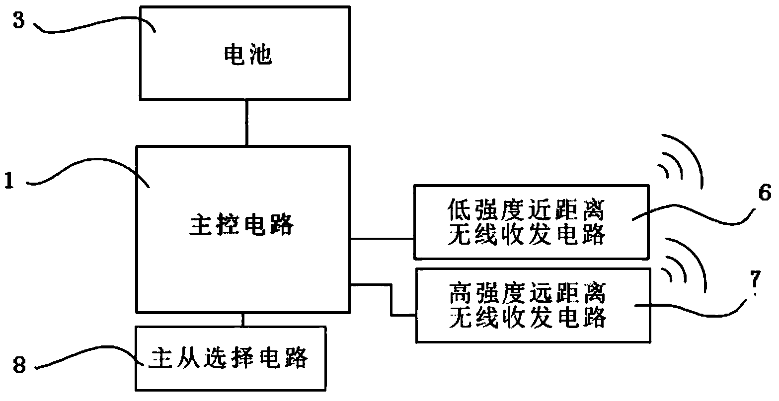
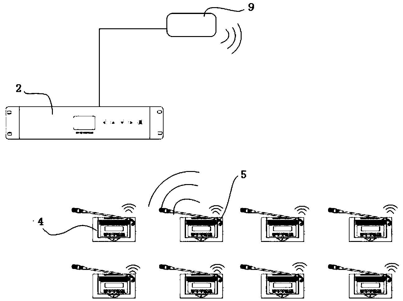
[0026] Such as figure 1 and figure 2 As shown, this example provides a wireless conference system, including: a host 2 connected to each other, a wireless data transceiver device 9, and at least two wireless conference units; wherein, the wireless conference unit includes a battery 3, a main control circuit 1, The low-intensity short-distance wireless transceiver circuit 6 and the high-intensity long-distance wireless transceiver circuit 7, the battery 3, the low-intensity short-distance wireless transceiver circuit 6 and the high-intensity long-distance wireless transceiver circuit 7 are respectively connected to the main control circuit 1; The low-intensity short-range wireless transceiver circuit 6 is used for data transmission before the wireless conference unit; the high-intensity long-distance wireless transceiver circuit 7 is used for data and communication between the host computer 2 and / or the wireless data transceiver device 9 and the wireless conference unit Trans...

Embodiment 2

[0032] On the basis of Embodiment 1, the main unit 5 described in this example is used to communicate with the host 2 to transmit audio and control signals; the slave unit 4 turns on the low-intensity short-range wireless transceiver circuit 6, and passes the signal The short-distance wireless transceiver circuit 6 transmits the data to the master unit 5; the master unit 5 summarizes the data of all the slave units 4 under its coverage, and then communicates the data with the host computer 2.

[0033] On the basis of setting two transceiver circuits in the wireless conference unit, this example also selects one or several wireless conference units in the entire conference venue as the master unit 5 through a certain control and selection mechanism, that is, the master-slave selection circuit 8 , other units serve as the auxiliary slave unit 4, the slave unit 4 transmits the data to the master unit 5, and the master unit 5 then transmits the summarized data to the host 2, or tra...

Embodiment 3

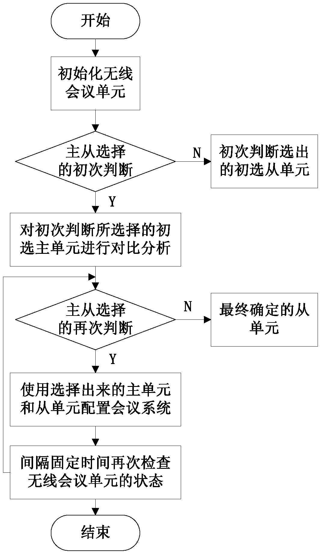
[0036] Such as image 3 As shown, on the basis of Embodiment 1 or Embodiment 2, this example first initializes the wireless conference unit, and then calculates the number of times each wireless conference unit speaks within a specific time, the speaking time, and each The identity of the wireless conference unit is used to make the initial judgment of the master-slave unit 4, and the primary judgment master unit and the primary slave unit are obtained; then, the primary judgment master unit selected for the initial judgment is compared and analyzed to realize a second judgment. The factors for re-judgment include the current power of the primary selected master unit 5, the signal strength received from the host 2 or the host transmitter unit, and the degree of interference of surrounding signals, and then the final master unit 5 and slave unit 4 are selected again, and according to The selected master unit 5 and slave unit 4 configure the wireless conference system; finally, ...


PUM


Abstract

The invention provides a wireless conference system which comprises a host, a wireless data transmitting and receiving device and at least two wireless conference units which are mutually connected. Each wireless conference unit comprises a battery, a main control circuit, a low-strength short-distance wireless transmitting-receiving circuit and a high-strength long-distance wireless transmitting-receiving circuit, wherein the battery, the low-strength short-distance wireless transmitting-receiving circuit and the high-strength long-distance wireless transmitting-receiving circuit are connected with the main control circuit respectively. The low-strength short-distance wireless transmitting-receiving circuits are used for data transmitting among the wireless conference units, and the high-strength long-distance wireless transmitting-receiving circuits are used for transmitting of the data and control signals among the host and / or the wireless data transmitting-receiving device and the wireless conference units. By means of the wireless conference system, electric quantity and transmitted power of every wireless conference unit are utilized reasonably according to actual situations, unnecessary transmitting power consumption is reduced, and the disadvantages of unreasonable role assignments of the wireless conference units and mismatching of the electric quantity, signal strength with actual requirements and the like are avoided.

Description

technical field [0001] The invention relates to a conference system, in particular to a wireless conference system. Background technique [0002] The current wireless conference system communicates with the conference units through a wireless transmitter receiver arranged in the venue, and the size of the venue (the number of conference units) is limited by the communication distance between the wireless transmitter receiver and the unit. The host of this kind of wireless conference system realizes the reception and transmission of the conference unit signal through an external or built-in wireless receiver and transmitter, and only one receiving and transmitting circuit is placed in each unit, so it must face several problems : First, the power of the power supply battery is fixed, and the use time of each charge of the battery is limited. Due to the difference in the frequency and duration of speeches in the venue, some conference units in the venue will quickly run out of...

Claims


Application Information

Patent Timeline
IPC IPC(8): H04L12/18H04L29/06H04L12/917H04L47/76
Inventor 许忠
Owner 方图智能(深圳)科技集团股份有限公司
Features
  • Generate Ideas
  • Intellectual Property
  • Life Sciences
  • Materials
  • Tech Scout
  • Unparalleled Data Quality
  • Higher Quality Content
  • 60% Fewer Hallucinations
Learn More