Equipment for fluid quantitative injection

A quantitative injection and equipment technology, applied in the manufacturing field, can solve the problems of large time error of pneumatic valves, high maintenance costs, and inaccurate injection volume of pneumatic fluid injection equipment.

Active Publication Date: 2014-07-02
ECOVACS ROBOTICS (SUZHOU ) CO LTD
View PDF6 Cites 11 Cited by
  • Summary
  • Abstract
  • Description
  • Claims
  • Application Information

AI Technical Summary

Problems solved by technology

However, the injection volume of this pneumatic fluid injection device is not accurate enough
First of all, it is not easy to precisely control the operation time of the above-mentioned fluid injection equipment, which is specifically manifested in the large time error of manual or automatic opening and closing of pneumatic valves; secondly

Method used


Image

  • Equipment for fluid quantitative injection
  • Equipment for fluid quantitative injection
  • Equipment for fluid quantitative injection

Examples


Embodiment 1

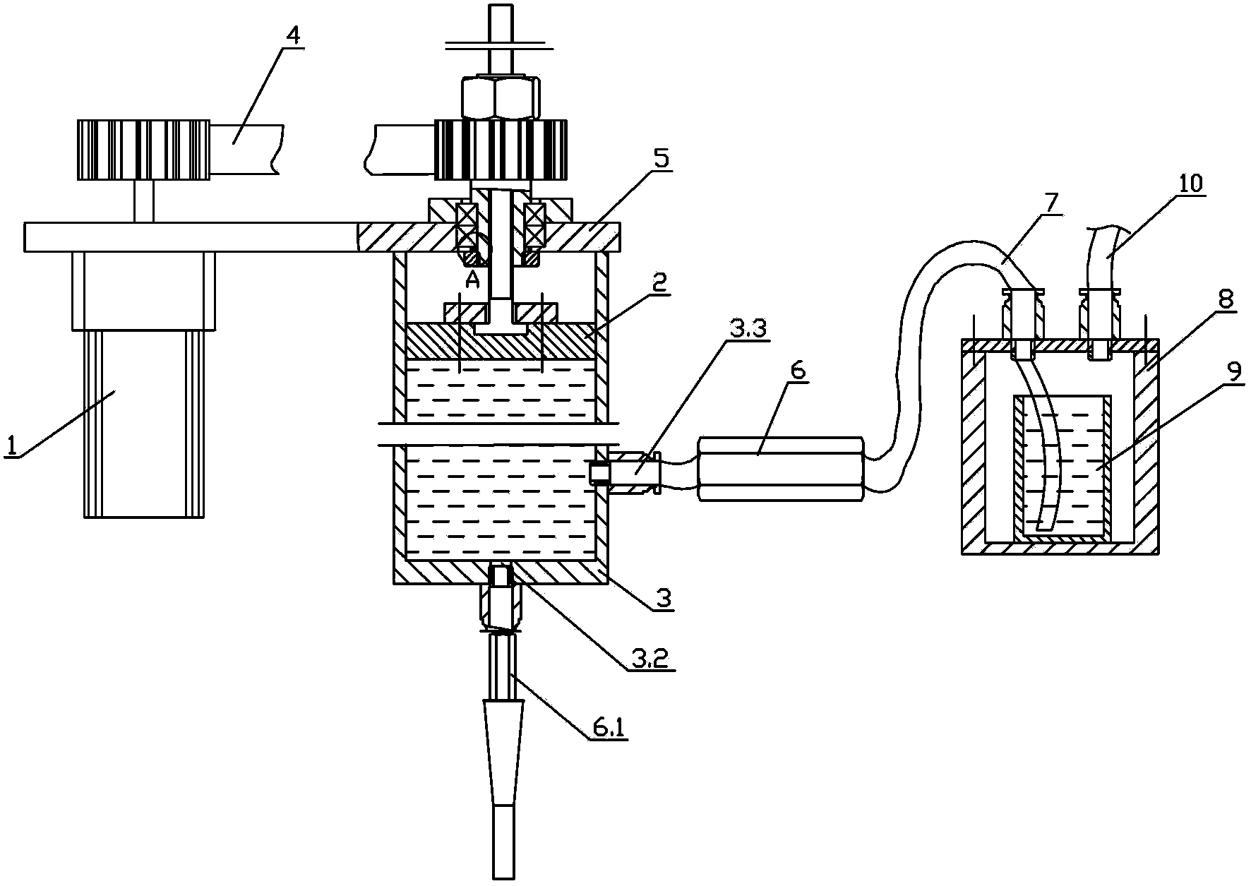
[0033] Such as Figure 1-4 , Image 6 As shown, in the fluid quantitative injection device of the present invention, the power mechanism 1 and the piston mechanism 2 are fixed on the base plate 5 , and the power mechanism 1 and the piston mechanism 2 are connected by a timing belt 4 .

[0034] The piston mechanism 2 in the power mechanism 1 is installed in the cylinder body 3; the cylinder body 3 is fixed on the base plate 5, the second one-way valve 6.1 is fixed on the discharge port 3.2, and one end of the delivery pipe 7 passes through the first one-way valve 6 is connected with the cylinder body 3, the other end of the delivery pipe 7 is inserted into the bottom of the barrel 9 through the pressure cylinder 8, and one end of the compressed air pipe 10 is connected with the pressure cylinder 8.

[0035] The power mechanism 1 can adopt the following two technical solutions.

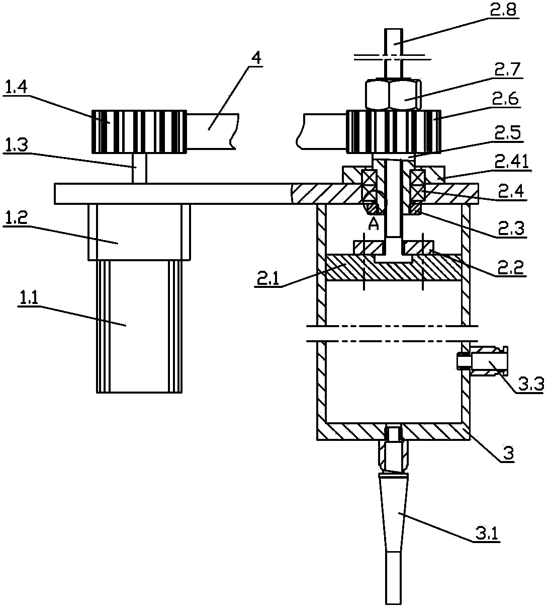
[0036] Such as figure 2 As shown, the power mechanism 1 includes a motor 1.1, a reducer 1.2 and ...

Embodiment 2

[0044] The main difference between the second embodiment and the first embodiment lies in the structure of the power mechanism and the connection relationship with the piston mechanism.

[0045] Such as Figure 5 as shown, Figure 5 It is a schematic diagram of the connection between another power mechanism and the piston mechanism in the fluid quantitative injection device of the present invention. The power mechanism 1 includes a motor 1.1, a reducer 1.2 and a motor output shaft 1.3, and the motor 1.1 is connected with the reducer 1.2. The transmission nut 2.5 in the piston mechanism 2 is arranged inside the speed reducer 1.2, and cooperates with the screw rod 2.8, and the screw rod 2.8 is connected with the piston 2.1 through the first end cover 2.2.

[0046] Combine below figure 1 , Figure 5 Describe the working principle of the fluid quantitative injection device of the present invention.

[0047]When the motor 1.1 in the power mechanism 1 rotates forward, the outpu...


PUM


Abstract

The invention belongs to the technical field of manufacturing, and relates to equipment for fluid quantitative injection. The injection equipment comprises a power mechanism (1), a piston mechanism (2), and a cylinder body (3); wherein the piston mechanism (2) comprises a transmission nut (2.5), a screw rod (2.8), and a piston (2.1); the power mechanism (1) is connected to the transmission nut (2.5) and drives the transmission nut (2.5) to rotate; then the transmission nut (2.5) drives the screw rod (2.8) to drive the piston (2.1) to move in a straight line in the cylinder body (3); the piston (2.1) pushes the fluid in the cylinder body out of the cylinder body, and thus the quantitative injection is completed. The equipment is difficult to interfere by outer factors, and has the advantages of high quantitative precision, simple structure, and easy maintenance.

Description

technical field [0001] The invention belongs to the field of manufacturing technology and relates to a fluid quantitative injection device. Background technique [0002] At present, in the process of automatic dispensing and lubricating grease, the fluid injection equipment drives the fluid to flow in the pipeline through compressed air or a high-pressure pump, and controls the injection volume by controlling the opening and closing time of the pneumatic valve. However, the pneumatic fluid injection device is not accurate enough to inject volume. First of all, it is not easy to precisely control the operation time of the above-mentioned fluid injection equipment, which is specifically manifested in the large time error of manual or automatic opening and closing of pneumatic valves; secondly, the liquid flow is particularly susceptible to air pressure fluctuations and interference from external factors, and also Due to the pneumatic control, it is necessary to maintain relat...

Claims


Application Information

Patent Timeline
IPC IPC(8): B05C5/02B05C11/10
Inventor 刘树元杨柏水
Owner ECOVACS ROBOTICS (SUZHOU ) CO LTD
Why Eureka
Try Eureka