Sheet material feeding and conveying device

A technology for conveying devices and sheets, applied in storage devices, feeding devices, positioning devices, etc., can solve the problems of insurmountable slippage, high sheet loss, and inability to absorb sheets, etc., to achieve convenient and accurate lifting control transmission, and production. High efficiency and smooth feeding effect

Active Publication Date: 2014-07-02
FUJIAN FUZHEN METAL PACKING CO LTD
View PDF6 Cites 20 Cited by
  • Summary
  • Abstract
  • Description
  • Claims
  • Application Information

AI Technical Summary

Problems solved by technology

[0002] The thin plate feeder in the can body production line has a certain height due to the plastic sucker that absorbs the thin plate. The plastic sucker needs to be lifted to a certain position before the plastic sucker can absorb the thin plate. The existing thin plate lifting device is usually manually adjusted to form a stack of thin plates. However, manual adjustment is likely to cause insufficient height. The plastic suction cup cannot absorb the thin plate, or the height of the rise is too high. The plastic suction cup is easily damaged when it hits the thin plate. It needs to be stopped for adjustment. , low work efficiency
[0003] The thin sheets need to be conveyed one by one during the conveying process, so as to facilitate the processing of the subsequent process. However, during the conveying process of the existing transmission belt, due to the long-term use of its upper end surface, the friction force decreases, and the thin sheets will slip on the conveying belt. It cannot be conveyed forward with the conveyor belt, and scratches or jams will occur, resulting in high loss of thin sheets and low production efficiency, especially when producing aluminum sheets, even if a magnet is installed on the bottom side of the conveyor belt, the slippage cannot be overcome

Method used


Image

  • Sheet material feeding and conveying device
  • Sheet material feeding and conveying device
  • Sheet material feeding and conveying device

Examples


Embodiment Construction

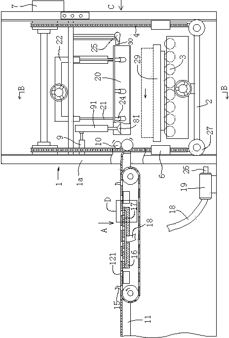
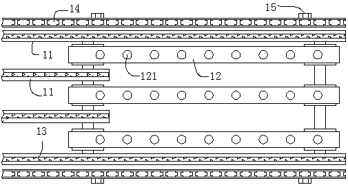
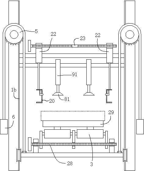
[0021] refer to Figure 1 to Figure 5 , a sheet material feeding and conveying device, including a frame 1 with columns 1a on both sides of the conveying production line, the lower part of the frame is provided with an elevator base 2, and a row is provided on the base for supporting stacked The transmission drum 3 of the thin plate is connected with the suspension chain 4 used to drive the machine base up and down on both sides of the front and rear sides of the machine base respectively. 6. The front and rear transmission sprockets located on the same side are driven by the same stepping motor 7 transmission mechanism, and the front and rear sides above the base are respectively provided with two lifting suction cups arranged in parallel and used to absorb thin plates. The lifting suction cup 81 is connected with the horizontal cylinder 9 connected on the frame to drive it to reciprocate forward and backward. A pair of horizontal rollers 10 are arranged on the front side of ...


PUM


Abstract

The invention relates to a sheet material feeding and conveying device. The sheet material feeding and conveying device comprises a rack which is located on the two sides of a conveying production line and provided with stand columns, a lifting machine base is arranged on the lower portion of the rack, a row of transmission rollers used for supporting stacked sheets is arranged on the machine base, sling chains are connected beside the front side and the rear side of the machine base respectively and used for driving the machine base to ascend and descend, the sling chains stride transmission chain wheels on the rack respectively, and a sling sinker used for balancing weight is arranged at the outer side end of each sling chain; the front transmission chain wheel and the rear transmission chain wheel on the same side are driven by a same stepping motor transmission mechanism; the front side and the rear side of the upper portion of the machine base are respectively provided with a lifting sucker used for adsorbing the sheets, the lifting sucker on the front side is connected with a transverse air cylinder connected to the rack so that the lifting sucker on the front side can be driven to move front and back in a reciprocating mode, the front side of the lifting sucker on the front side is provided with a pair of horizontal rollers used for drawing the sheets to move forward, and the output end of each horizontal roller is provided with a sheet conveying device. Not only is the sheet material feeding and conveying device beneficial for guiding a sheet bearing base from the production line, but also lifting control and transmission are convenient and accurate, and feeding is smooth.

Description

technical field [0001] The invention relates to a sheet material feeding and conveying device. Background technique [0002] The thin plate feeder in the can body production line has a certain height due to the plastic sucker that absorbs the thin plate. The plastic sucker needs to be lifted to a certain position before the plastic sucker can absorb the thin plate. The existing thin plate lifting device is usually manually adjusted to form a stack of thin plates. However, manual adjustment is likely to cause insufficient height. The plastic suction cup cannot absorb the thin plate, or the height of the rise is too high. The plastic suction cup is easily damaged when it hits the thin plate. It needs to be stopped for adjustment. , low work efficiency. [0003] The thin sheets need to be conveyed one by one during the conveying process, so as to facilitate the processing of the subsequent process. However, during the conveying process of the existing transmission belt, due to...

Claims


Application Information

Patent Timeline
Patent Type & Authority Applications(China)
IPC IPC(8): B21D43/02B21D43/12B21D43/18B21D43/08
Inventor 林德锦
Owner FUJIAN FUZHEN METAL PACKING CO LTD
Why Eureka
Try Eureka