
Batch machining device and machining technology for multiple holes uniformly formed in circumferences

A batch processing, circular technology, applied in the direction of tangent device, metal processing equipment, metal processing machinery parts, etc., can solve the problems of only processing one by one, low work efficiency, etc., to achieve the effect of improving work efficiency

Inactive Publication Date: 2014-07-02
梁满伦 +2
View PDF0 Cites 15 Cited by
  • Summary
  • Abstract
  • Description
  • Claims
  • Application Information

AI Technical Summary

Problems solved by technology

But for small holes with relatively small hole pitches, the above technical scheme is limited, because the supporting bearings of the drill bits occupy a certain space, so that the distance between adjacent drill bits is limited by the supporting bearings, resulting in the hole pitch of adjacent small holes Can not be less than the center distance of two adjacent support bearings, when the hole distance of adjacent small holes is smaller than the center distance of two adjacent support bearings, it can only be processed one by one, and the work efficiency is very low

Method used


Image

  • Batch machining device and machining technology for multiple holes uniformly formed in circumferences
  • Batch machining device and machining technology for multiple holes uniformly formed in circumferences
  • Batch machining device and machining technology for multiple holes uniformly formed in circumferences

Examples


Embodiment 2

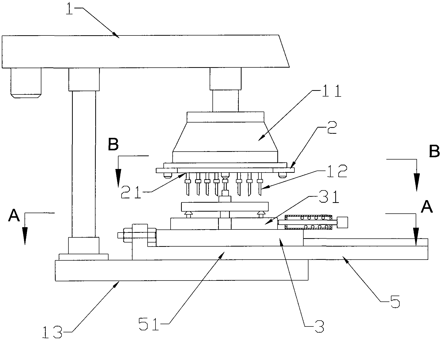
[0046] This embodiment is basically the same as Embodiment 1, the difference is that, see Figure 5 , also includes a drill guide plate 4, the drill guide plate 4 is placed under the drill template base plate 2, and the distance between the drill guide plate 4 and the drill template base plate 2 is less than the length of the drill bit or the thread tap 12.

[0047] Example 1 of the processing technology for batch processing the holes evenly distributed on the hole distribution circle

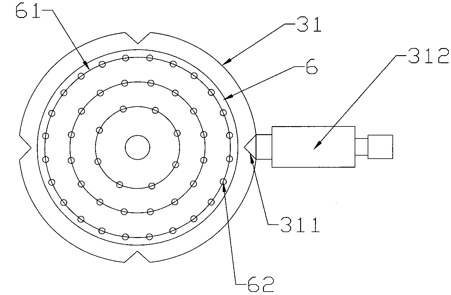
[0048] Look back image 3 , the present embodiment processes a plurality of circular holes or threaded holes 62 evenly distributed on the circumference of the hole, and there are 4x6, 4x4, and 4x2 circular holes or threaded holes 62.

[0049] first step, look back figure 1 , install and fix the group drill bit assembly or group screw tap assembly 11 on the vertical hydraulic drilling machine 1, install and fix the indexing fixture 3 with the turntable index plate 31 under the base plate 2 of ...


PUM


Abstract

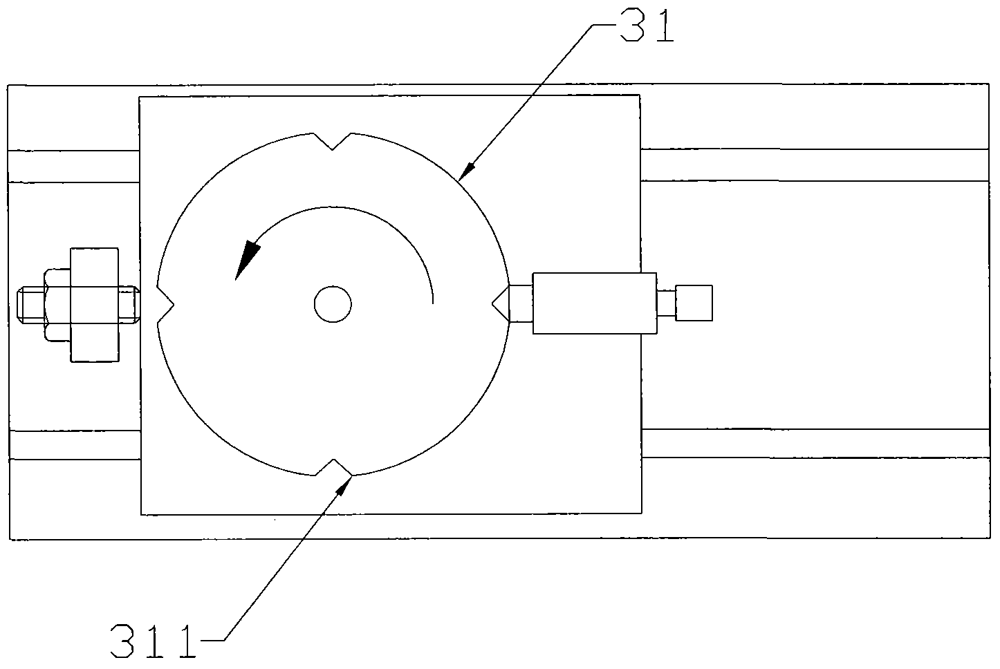
The invention discloses a batch machining device for multiple holes uniformly formed in circumferences. The batch machining device comprises a vertical hydraulic drilling machine, a base plate and an indexing fixture. The vertical hydraulic drilling machine is provided with a grouped drill bit assembly or grouped screw tap assembly with n drill bits or screw taps; bearing positioning holes are formed in the base plate, and the drill bits or screw taps are supported in the bearing positioning holes via bearings; the indexing fixture is provided with a turntable indexing plate; the bearing positioning holes are distributed on the central circumference of the drill base plate, the central circumference of the drill base plate and hole distribution circumferences are coaxial with one another and have equal diameters, each bearing positioning hole and one of circular holes or threaded holes in the hole distribution circumferences are coaxial with each other, and the circular holes or threaded holes are uniformly distributed on the hole distribution circumferences; the turntable indexing plate and the central circumference of the drill base plate are coaxial with each other, m indexing bolt openings are uniformly formed in the circumferential edge of the turntable indexing plate, the turntable indexing plate is divided into m intervals by radial lines which extend from the center of the turntable indexing plate to the indexing bolt openings, and the circular holes or threaded holes are uniformly distributed in the various intervals. The invention further discloses a batch machining technology for the multiple holes uniformly formed in the circumferences. The batch machining device and the batch machining technology have the advantages of simple structure and applicability to places where components with multiple holes, small diameters and short center distances are available.

Description

technical field [0001] The invention relates to a device for batch processing the holes evenly distributed on the circumference, and also relates to a processing technology for batch processing the holes evenly distributed on the circumference. Background technique [0002] In the prior art, when the holes evenly distributed on the circumference are processed, the holes on the circumference of the parts to be processed are processed simultaneously by a vertical hydraulic drilling machine using a group drill assembly or a group tap assembly, and the group drill assembly or The number of drill bits or taps in the screw tapping assembly is equal to the number of holes on the circumference, so that the processing of holes can be completed in one operation. But for small holes with relatively small hole pitches, the above technical scheme is limited, because the supporting bearings of the drill bits occupy a certain space, so that the distance between adjacent drill bits is limit...

Claims


Application Information

Patent Timeline
IPC IPC(8): B23B39/16B23B49/00B23B35/00B23G1/08B23Q16/06B23Q1/25
CPCB23B39/161B23B35/00B23B49/00B23G1/08B23Q1/25B23Q16/06
Inventor 钟柏活
Owner 梁满伦
Learn More