Energy-saving air-jet loom

An air-jet loom, energy-saving technology, applied in looms, textiles, textiles and papermaking, etc., can solve the problems of large air consumption, large capital investment, pipeline loss and waste, etc., to increase stability and reliability, reduce Weaving cost, high cost effect

Inactive Publication Date: 2014-07-02
QINGDAO TIANYI GROUP RED FLAG TEXTILE MACHINERY
View PDF6 Cites 6 Cited by
  • Summary
  • Abstract
  • Description
  • Claims
  • Application Information

AI Technical Summary

Problems solved by technology

The construction of such a special gas supply station requires a large capital investment, high operation and maintenance costs, large gas consumption, and serious waste of pipeline losses; even if the number of startups is small, the entire gas supply station system needs to be turned on, and the weaving cost is affected by the startup rate. very big

Method used


Image

  • Energy-saving air-jet loom
  • Energy-saving air-jet loom
  • Energy-saving air-jet loom

Examples


Embodiment 1

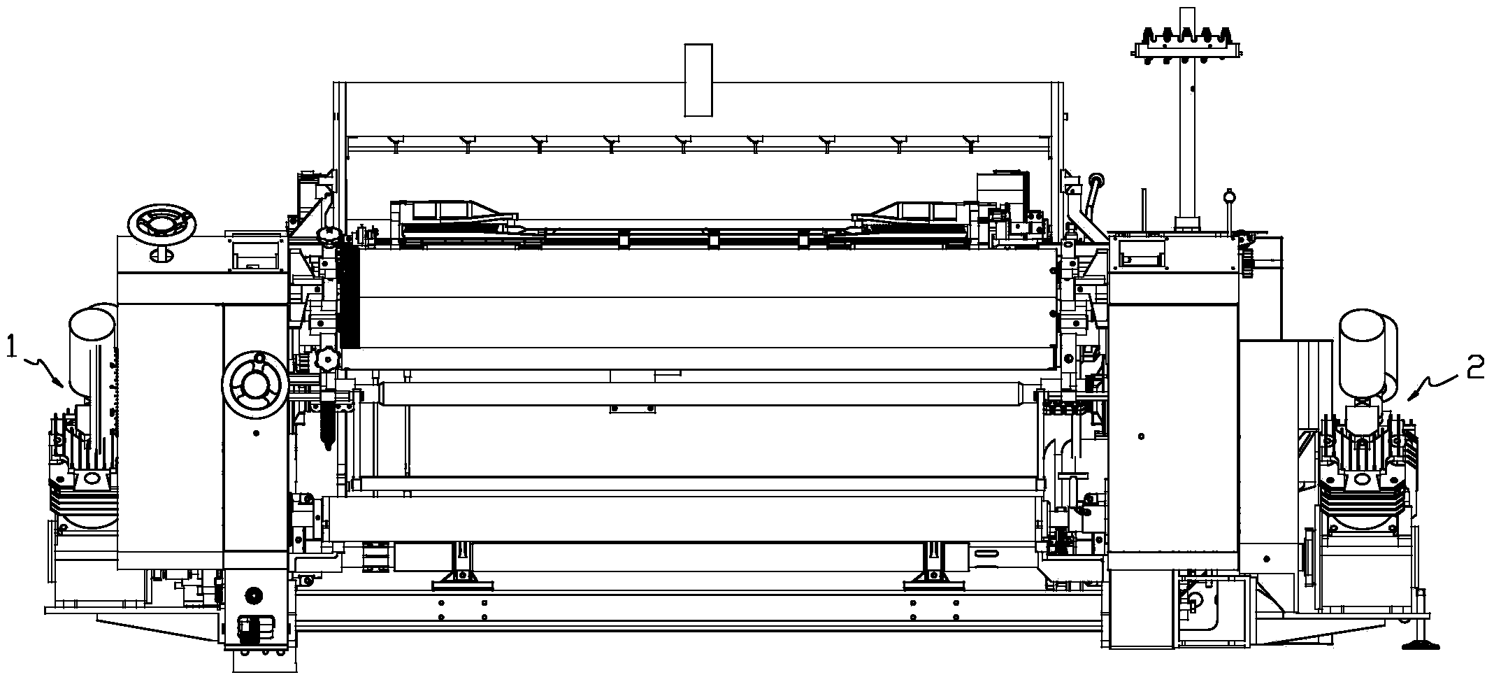
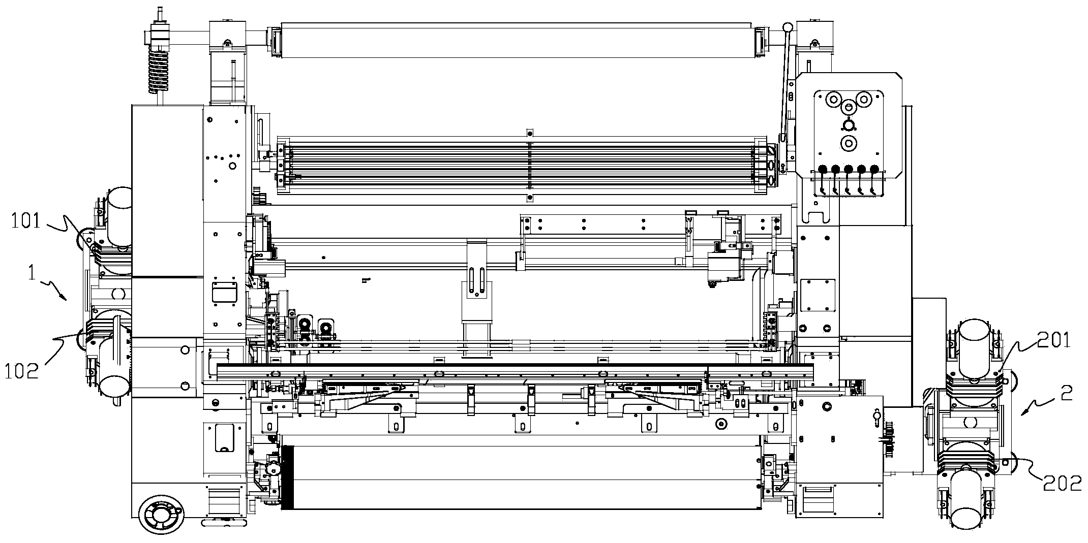
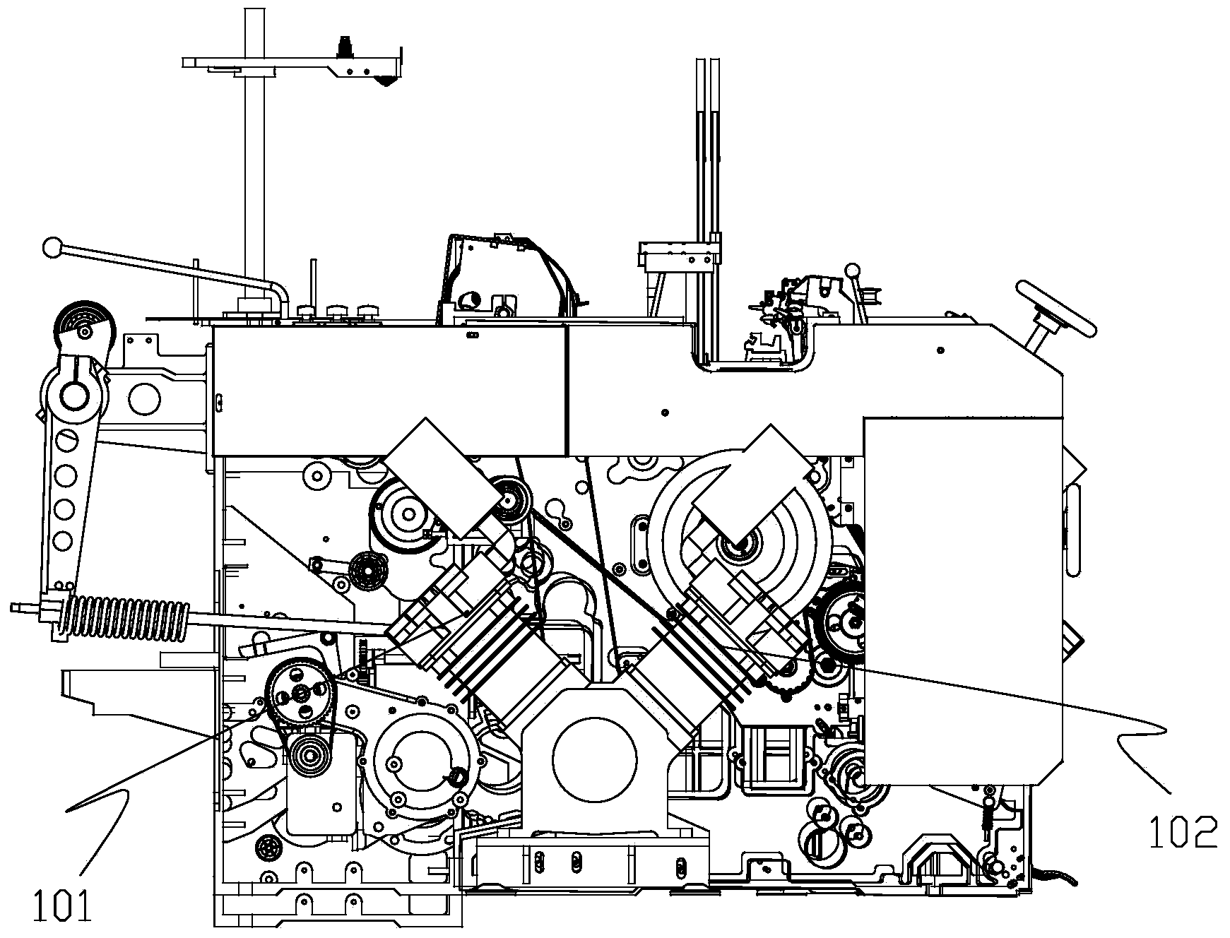
[0028] combine figure 1 , figure 2 , image 3 , Figure 4 , Figure 5 and Figure 6, an energy-saving air-jet loom, comprising a frame and an air-jet weft insertion mechanism. The air jet weft insertion mechanism includes a first air pump 1 , a second air pump 2 , a main nozzle group 3 and an auxiliary nozzle group 4 . The above-mentioned main nozzle group has at least one main nozzle 301, and the auxiliary nozzle group has several auxiliary nozzles 401 arranged in sequence on the weft flight path. The first air pump is arranged on one side of the frame, and it includes a main plunger cylinder 101 and an auxiliary plunger cylinder 102. The two plunger cylinders are connected as one, and the piston rods of the two plunger cylinders are connected to the On the crankshaft, the crankshaft is connected to the power spindle of the loom, that is, the power spindle of the loom drives the main plunger cylinder and the auxiliary plunger cylinder to run through the crankshaft; of ...

Embodiment 2

[0034] to combine Figure 7 , except for the following content, other technical content may be the same as the corresponding part of Embodiment 1.

[0035] An energy-saving air jet loom comprises a frame and an air jet weft insertion mechanism, including a frame and an air jet weft insertion mechanism. The air jet weft insertion mechanism includes a first air pump, a second air pump, a main nozzle group and an auxiliary nozzle group. The above-mentioned main nozzle group has at least one main nozzle, and the auxiliary nozzle group has several auxiliary nozzles arranged in sequence on the weft flight path. The first air pump is set on the side wall of the frame, which includes a main plunger cylinder and an auxiliary plunger cylinder. The two plunger cylinders are connected as a whole, and the piston rods of the two plunger cylinders are connected to the same crankshaft. , the crankshaft is connected to the power spindle of the loom, that is, the power spindle of the loom dri...


PUM


Abstract

The invention discloses an energy-saving air-jet loom comprising a frame and an air-jetting-flow weft insertion mechanism. The energy-saving air-jet loom is characterized in that the air-jetting-flow weft insertion mechanism comprises a first air pump, a main nozzle group and an auxiliary nozzle group; the main nozzle group at least comprises one main nozzle, and the auxiliary nozzle group comprises a plurality of auxiliary nozzles arrayed on weft flying lines sequentially; the first air pump is arranged on a wallboard of one side of the frame and comprises a main plunger type cylinder and an auxiliary plunger type cylinder which are connected integrally, and the piston links of the two plunger type cylinders are connected to one crankshaft which is connected to a loom power spindle; the exhausting end of the main plunger type cylinder of the first air pump is connected to the main nozzle through a pipeline, the exhausting end of the auxiliary plunger type cylinder is connected to the auxiliary nozzles in the auxiliary nozzle group through pipelines. By the aid of the energy-saving air-jet loom, weaving cost can be reduced greatly, the problems of high investment, high cost and high energy consumption of a high-grade loom can be solved; in addition, two air pumps can be adopted synchronously, relayed weft insertion can be implemented more effectively, and broad fabric weaving can be implemented.

Description

technical field [0001] The invention relates to an air-jet loom, in particular to an energy-saving air-jet loom. Background technique [0002] The air-jet loom is a shuttleless loom that adopts air jet weft insertion, that is, the jet airflow pulls the weft yarn through the shed. Due to its reasonable weft insertion method, high weft insertion rate, easy and safe operation, wide variety adaptability, and low machine material consumption Less, high efficiency, high speed, low noise and other advantages, and become one of the most promising new looms. With the expansion of the weaving range of the textile industry, the increase of the application range of the air-jet loom, the change of the weaving environment, and the increase of varieties, many users urgently need to choose a suitable energy-saving air-jet loom for low-cost and high-end weaving products. Cost weaving, and existing air-jet loom can not satisfy such demand well. The above-mentioned air-jet looms all use a ce...

Claims


Application Information

Patent Timeline
Patent Type & Authority Applications(China)
IPC IPC(8): D03D47/30
Inventor 齐立民赵付斌范龙霄吴海艳孙士省丁兵强逄浩然霍艳慧
Owner QINGDAO TIANYI GROUP RED FLAG TEXTILE MACHINERY
Why Eureka
Try Eureka