Multi-axial fixed geometrical pneumatic vectoring nozzle structure

A fixed geometry, vector nozzle technology, applied in the direction of machines/engines, jet propulsion devices, etc., can solve the problems of heavy nozzle weight, low reliability, poor stealth ability, etc., to achieve easy large-scale promotion and application, ingenious concept Novel, simple and reasonable structure

Inactive Publication Date: 2014-07-02
NORTHWESTERN POLYTECHNICAL UNIV
View PDF4 Cites 6 Cited by
  • Summary
  • Abstract
  • Description
  • Claims
  • Application Information

AI Technical Summary

Problems solved by technology

[0003] Considering the inherent disadvantages of the mechanical thrust vectoring nozzle: heavy weight of the nozzle, large number of moving parts in a high temperature environment, high cooling requirements, poor stealth ability, low reliability, and high cost, more and more domestic and foreign Many researchers have begun to explore new types of thrust vectoring nozzles to replace the mechanically-adjustable-pneumatic thrust vectoring nozzles, that is, through secondary flow control, the direction of the mainstream can be changed.
The main feature of various types of fixed-geometry aerodynamic vectoring nozzles studied in recent years is that they can only achieve thrust vectoring control in one direction, that is, they can only perform pitching thrust vectoring control or yaw thrust vectoring control, which cannot meet the modern requirements. Requirements of Fighter Aircraft for Aeroengine Exhaust System Thrust Vectoring Multifunction

Method used


Image

  • Multi-axial fixed geometrical pneumatic vectoring nozzle structure
  • Multi-axial fixed geometrical pneumatic vectoring nozzle structure
  • Multi-axial fixed geometrical pneumatic vectoring nozzle structure

Examples


Embodiment Construction

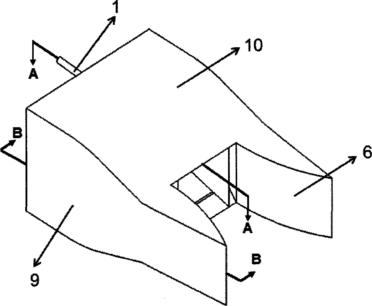
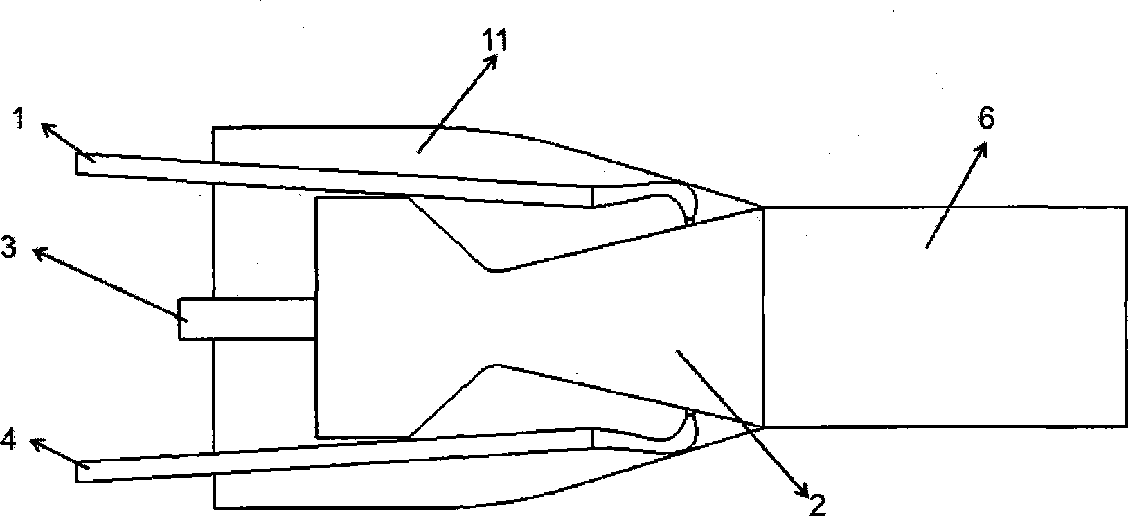
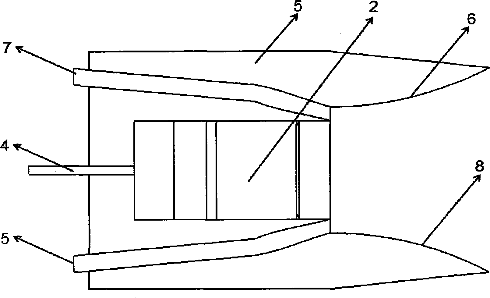
[0016] Referring to each figure, the present invention is a multi-axis fixed geometry aerodynamic vector nozzle structure, which is characterized in that the structure includes: the upper high-pressure secondary flow injection pipeline 1 and the lower high-pressure secondary flow injection pipeline 4 are arranged in a rectangular convergence-expansion The upper and lower sides of the nozzle 2 are composed of circular and square pipes, and the circular pipe sections of the upper high-pressure secondary flow injection pipe 1 and the lower high-pressure secondary flow injection pipe 4 are connected with the air release system of the high-pressure components of the aeroengine such as fans and compressors. , and a throttling device is set on the connecting pipe to control the flow rate of the high-pressure secondary flow; the secondary flow suction pipes 3 and 7 are on the left and right sides of the rectangular convergent-divergent nozzle, named as the left secondary flow suction pi...


PUM


Abstract

Disclosed is a multi-axial fixed geometrical pneumatic vectoring nozzle structure. The multi-axial fixed geometrical pneumatic vectoring nozzle structure is composed of an upper high-pressure secondary flow injection pipe, a lower high-pressure secondary flow injection pipe, a rectangular convergent-divergent nozzle, a left secondary flow suction pipe, a right secondary flow suction pipe, a left Coanda curved surface, a right Coanda curved surface and a skin connected with the nozzle and an airframe. A thrust vectoring state and a non-thrust vectoring state exist during normal operation, and only the high-pressure secondary flow injection pipes and the secondary flow suction pipes need to be closed at the same time for the non-thrust vectoring state. For vectoring conditions, if pitch thrust vectoring needs to be realized, only the high-pressure secondary flow injection pipes are opened, and pitch thrust vectoring angles can be controlled by means of control on flow and pressure of high-pressure secondary flow entering the pipes; if yaw thrust vectoring needs to be realized, the secondary flow suction pipes need to be connected with a vacuum suction device, and different yaw vectoring angles are realized by control on vacuum degree of the vacuum suction device; if pitch control and yaw control are needed at the same time, the two above processed need to be combined.

Description

Technical field: [0001] The invention relates to the technical field of aero-engines, in particular to a novel exhaust system structure applied to aero-engines, in particular to a multi-axis fixed geometry aerodynamic vector nozzle structure. Background technique: [0002] Thrust Vectoring technology means that the power plant of an aircraft such as an aircraft or missile not only provides forward thrust for flight, but also deflects the thrust direction by controlling the mainstream of the nozzle, resulting in additional roll, pitch, and yaw. Navigation and reverse thrust torque, used to supplement or replace the control of aerodynamic rudder surfaces. According to the implementation method of thrust vectoring, it can be divided into mechanical thrust vectoring technology and fixed geometry aerodynamic thrust vectoring technology. [0003] Considering the inherent disadvantages of the mechanical thrust vectoring nozzle: heavy weight of the nozzle, large number of moving pa...

Claims


Application Information

Patent Timeline
Patent Type & Authority Applications(China)
IPC IPC(8): F02K1/78
Inventor 史经纬王占学孙啸林刘增文周莉章叶川
Owner NORTHWESTERN POLYTECHNICAL UNIV
Why Eureka
Try Eureka