
A boiler scr denitrification modification method and device

A technology for denitration transformation and boilers, which is applied to steam boilers, steam generation, lighting and heating equipment, etc. It can solve the problems of affecting ammonia-nitrogen mixing, lack of space, and complex systems, achieve uniform flue gas flow rate, reduce transformation costs, and increase height. Effect

Active Publication Date: 2016-02-10
SOUTHEAST UNIV
View PDF6 Cites 0 Cited by
  • Summary
  • Abstract
  • Description
  • Claims
  • Application Information

AI Technical Summary

Problems solved by technology

[0006] Purpose of the invention: In order to solve the problems existing in the prior art, the present invention proposes a boiler SCR denitrification transformation method, which is mainly aimed at the SCR denitrification transformation method for boilers with economizer and air preheater two-stage staggered arrangement, so as to solve the problem of When the double-stage staggered layout of the economizer and the air preheater is used for SCR denitrification transformation, there is insufficient space for the denitrification outlet flue and the introduction flue to be installed in the temperature window of the shaft flue. The introduction of the flue and the high and low temperature air preheater to fight with the ventilation duct, the use of side-out and side-in renovation methods make the system complex and affect the mixing of ammonia and nitrogen, and the amount of ammonia injection does not match the distribution of NOx when the operating parameters of the boiler change, etc.

Method used


Image

  • A boiler scr denitrification modification method and device
  • A boiler scr denitrification modification method and device

Examples


Embodiment Construction

[0030] Refer to the following Figure 1-2 The implementation of the present invention will be described in detail. This embodiment is carried out on the premise of this technical solution, and the detailed implementation and operation process are given, but the protection scope of the present invention is not limited to the following embodiments.

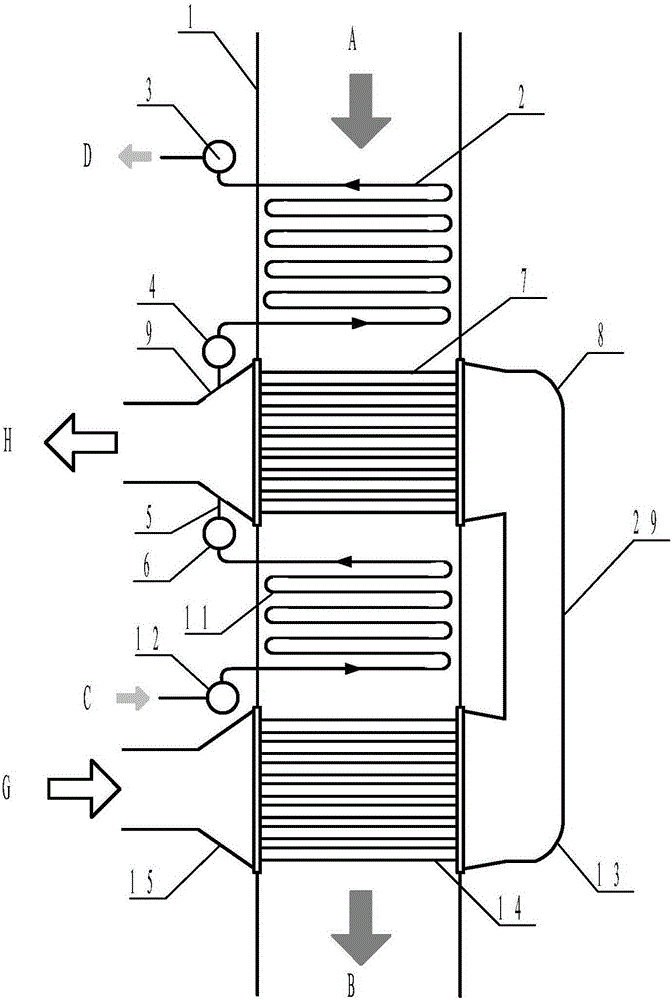
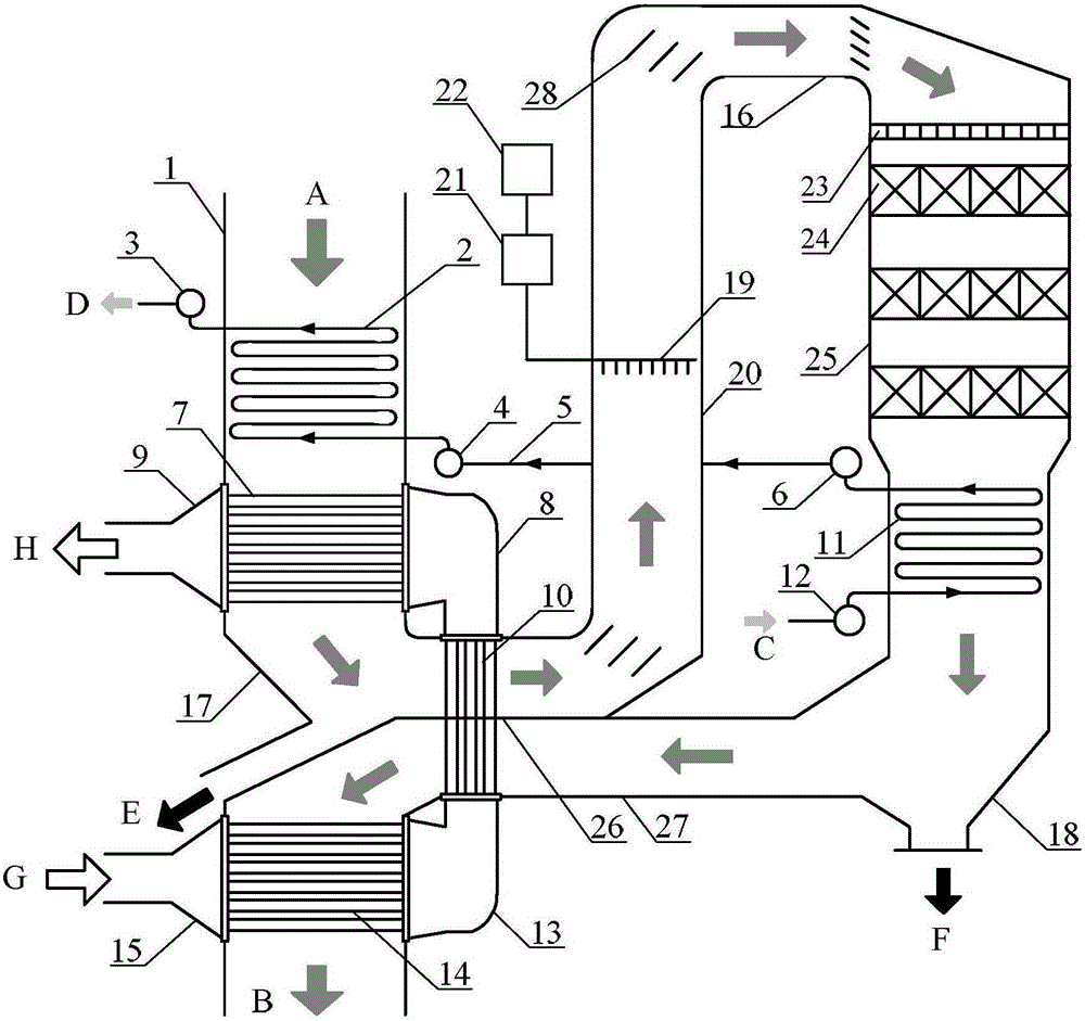
[0031] In this example, the SCR denitrification transformation is carried out for a 220t / h boiler in a certain power plant. Before the transformation, the heating surface at the tail of the boiler was arranged in the shaft flue 1 from high to low in order of high temperature economizer 2, high temperature air preheater 7, low temperature economizer 11 and low temperature air preheater 14, and the high temperature flue gas flowed from each The heating surface tubes flow outside, and the temperature gradually decreases. When the boiler is operating at rated load, the flue gas temperature between the high-temperature air preheater 7 a...


PUM


Abstract

The invention discloses an SCR (selective catalytic reduction) denitrification modification method and an SCR denitrification modification device for boilers. The SCR denitrification modification method and the SCR denitrification modification device are mainly used for the boilers with coal economizers and air preheaters which are arranged in a two-stage staggered manner. The SCR denitrification modification method includes shifting low-temperature coal economizers to SCR reactors; modifying communication air channels among high-temperature air preheaters and low-temperature air preheaters to form vertical air preheaters; arranging lead-out flues at the rears of the high-temperature air preheaters and enabling the lead-out flues to intersect with upper portions of the vertical air preheaters; enabling to-be-denitrated flue gas to flow through the outsides of pipes of the vertical air preheaters and flow into denitration reactors; arranging lead-in flues below the lead-out flues and enabling the lead-in flues to intersect with the lower portions of the vertical air preheaters; enabling denitrated flue gas to flow through the outsides of the pipes of the vertical air preheaters and flow into the low-temperature air preheaters. Problems of conflict among lead-out flues, lead-in flues and communication air channels and matching of ammonia and nitrogen under variable working conditions can be solved by the aid of the SCR denitrification modification method. The SCR denitrification modification method and the SCR denitrification modification device have the advantages of compact structure, high denitrification efficiency and the like.

Description

technical field [0001] The invention belongs to the technical field of selective catalytic reduction (SCR) denitrification, and in particular relates to a boiler SCR denitrification transformation method and device aimed at two-stage interlaced arrangement of an economizer and an air preheater. Background technique [0002] As my country's environmental protection regulations become increasingly stringent, more and more established power stations need to undergo technical transformation, and SCR denitrification devices are installed on the boilers to meet the requirements of emission standards. According to statistics, as of 2013, my country has completed denitrification transformation of 430 million kilowatts, and there are still about 400 million kilowatts that need to be denitrified. These old-fashioned boilers to be remodeled are usually equipped with multi-stage economizers and tube-type air preheaters in the tail shaft flue, with a compact structure, and a considerable...

Claims


Application Information

Patent Timeline
Patent Type & Authority Patents(China)
IPC IPC(8): F23J15/00F22B31/08
Inventor 张勇金保昇
Owner SOUTHEAST UNIV
Learn More