Workbench cable device

A technology of cable device and workpiece table, which is applied to the exposure device of photoengraving process, electrical components, photoengraving process of pattern surface, etc., can solve the problems of cable following, etc. The effect of simple mechanical structure and control algorithm

Active Publication Date: 2014-07-02
SHANGHAI MICRO ELECTRONICS EQUIP (GRP) CO LTD
View PDF6 Cites 8 Cited by
  • Summary
  • Abstract
  • Description
  • Claims
  • Application Information

AI Technical Summary

Problems solved by technology

[0006] The present invention provides a workpiece table cable device to solve the problem in the prior art that the cable passively follows the movement of the silicon wafer table

Method used


Image

  • Workbench cable device
  • Workbench cable device
  • Workbench cable device

Examples


Embodiment 1

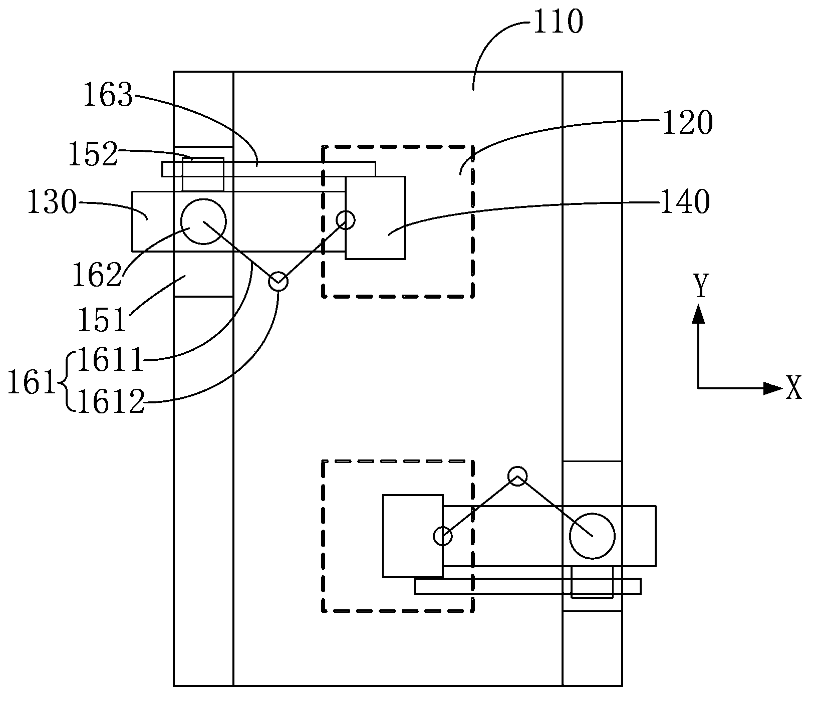
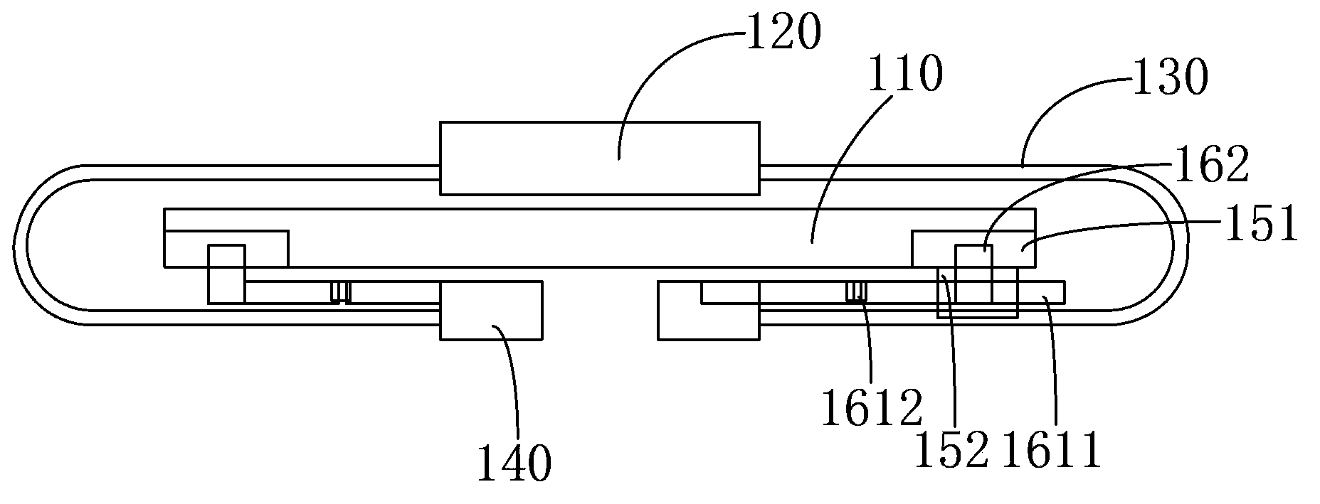
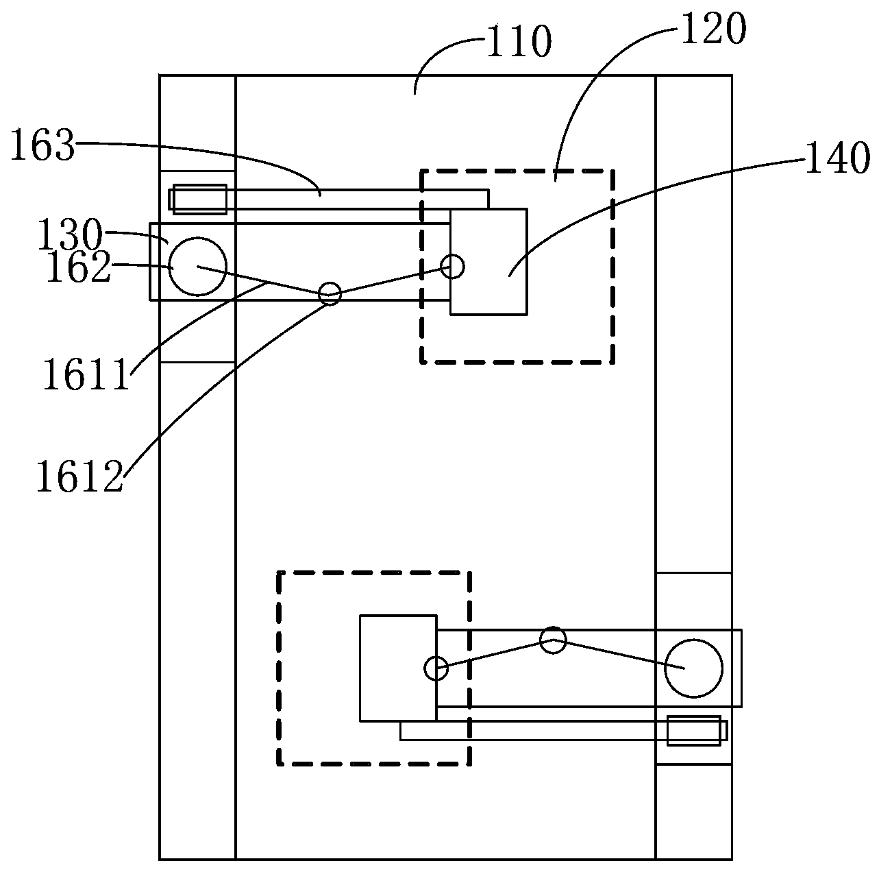
[0041] Please continue to refer Figure 1 to Figure 4, the Y-direction motion equipment includes a slide table 151 fixed on the bottom edge of the workpiece table 110 and a slide block 152 that can slide along the slide table 151, and the X-direction motion equipment includes a telescopic piece, a control motor and a guide device , the guiding device is arranged along the X direction, one end of the telescopic member and the guiding device are respectively installed on the slider 152, and the other ends are respectively installed on the cable connection table 140, and the control motor controls the Telescoping of telescopic parts. Preferably, the guide device is a guide rod 163. Preferably, the guide rod 163 is a linear guide device, and a mechanical bearing or an air bearing or a magnetic bearing is provided between the guide rod 163 and the slider 152. bearings. One end of the guide rod 163 is fixedly connected to the cable connection platform 140, and the other end of the...

Embodiment 2

[0050] Such as Figure 7 As shown, the difference between this embodiment and Embodiment 1 is that the telescopic member is a linear slide rail, and the linear slide rail includes a track 261 in the X direction and a fixed block 262 sliding along the track 261, and the track 261 One end of one end is fixedly connected to the slider 252, and the cable connection table 240 is fixed on the fixed block 262; the control motor is a linear motor (not shown in the figure), and the linear motor controls the fixed The block 262 moves linearly along the track 261. Preferably, the linear motor is also provided with a linear encoder (not shown in the figure). That is to say, the Y-direction motion equipment is the same as Embodiment 1, including a slide table 251 fixed on the bottom edge of the workpiece table 210 and a slide block 252 capable of sliding along the slide table 251; and in the X-direction motion equipment The telescopic part is a linear slide rail, such as a linear motor, a...

Embodiment 3

[0052] The difference between this embodiment and Embodiments 1 and 2 is that both the X-direction motion device and the Y-direction motion device are provided by a magnetic steel array or a coil array.

[0053] Preferably, please refer to Figure 8 with Figure 9 , the bottom of the workpiece table 310 is provided with a first magnetic steel array (or first coil array) 350, and the cable connection table 340 is provided with a Corresponding second magnetic steel array (or second coil array). The first magnetic steel array (or first coil array) 350 and the second magnetic steel array (or second coil array) form a planar motor, thereby controlling the movement of the cable connection table 340 in the X and Y directions. relative movement.

[0054] Preferably, please continue to refer to Figure 8 with Figure 9 , the wafer stage 320 is provided with a Hall sensor array (not shown in the figure), and a follower sensor (not shown in the figure) is provided between the cable ...


PUM


Abstract

A work station cable apparatus comprises a work station (110), a silicon wafer station (120), a cable device (130), a cable connection station (140), an X-direction moving device and a Y-direction moving device. The silicon wafer station (120) and the cable connection station (140) are respectively mounted on the upper side and the lower side of the work station (110). The two ends of the cable device (130) are connected to the silicon wafer station (120) and the cable connection station (140) respectively. The X-direction and Y-direction moving devices are both connected to the cable connection station (140) and respectively drive the cable connection station (140) to move following the silicon wafer station (120) along the X-direction and the Y-direction. The cable connection station (140) drives the cable device (130) to synchronously move following the silicon wafer station (120) along the X-direction and the Y-direction, thus being able to reduce disturbance of the cable device (130) to the motion of the silicon wafer station (120), reduce the bending times of the cable device (130) and prolong the service life of the cable device.

Description

technical field [0001] The invention relates to the field of semiconductor lithography equipment, in particular to a workpiece table cable device. Background technique [0002] In semiconductor lithography equipment, precision silicon wafer stage motion systems such as wafer stage and mask stage are extremely important key components. Their positioning accuracy directly affects the performance of lithography equipment, and their operating speed directly affects the production efficiency of lithography equipment. . With the continuous improvement of the integration of VLSI devices and the continuous enhancement of lithography resolution, the requirements for the characteristic line width index of lithography machines are also continuously improved, and the corresponding requirements for the operating speed, acceleration and accuracy of the silicon wafer stage are also increasing. keep improving. [0003] The typical structural form of the silicon wafer stage system of a lit...

Claims


Application Information

Patent Timeline
Patent Type & Authority Applications(China)
IPC IPC(8): G03F7/20
CPCG03F7/20G03F7/70716G03F7/709G03F7/70991H01L21/68764
Inventor 郭琳吴立伟陈军江旭初张志钢
Owner SHANGHAI MICRO ELECTRONICS EQUIP (GRP) CO LTD
Why Eureka
Try Eureka