Flyconnector for LED module board

A technology of LED modules and connectors, which is applied in the direction of connection, fixed connection, and parts of connection devices, etc., to achieve the effect of excellent assembly

Inactive Publication Date: 2014-07-02
SMK CO LTD
View PDF8 Cites 2 Cited by
  • Summary
  • Abstract
  • Description
  • Claims
  • Application Information

AI Technical Summary

Problems solved by technology

[0009] Also, Patent Document 2 discloses a technique of mounting an LED package on a heat sink so that a material having both thermal conductivity and electrical insulation is interposed therebetween, but the lighting device disclosed in the publication does not use a LED module substrate. Connector (cover part)

Method used


Image

  • Flyconnector for LED module board
  • Flyconnector for LED module board
  • Flyconnector for LED module board

Examples


Embodiment Construction

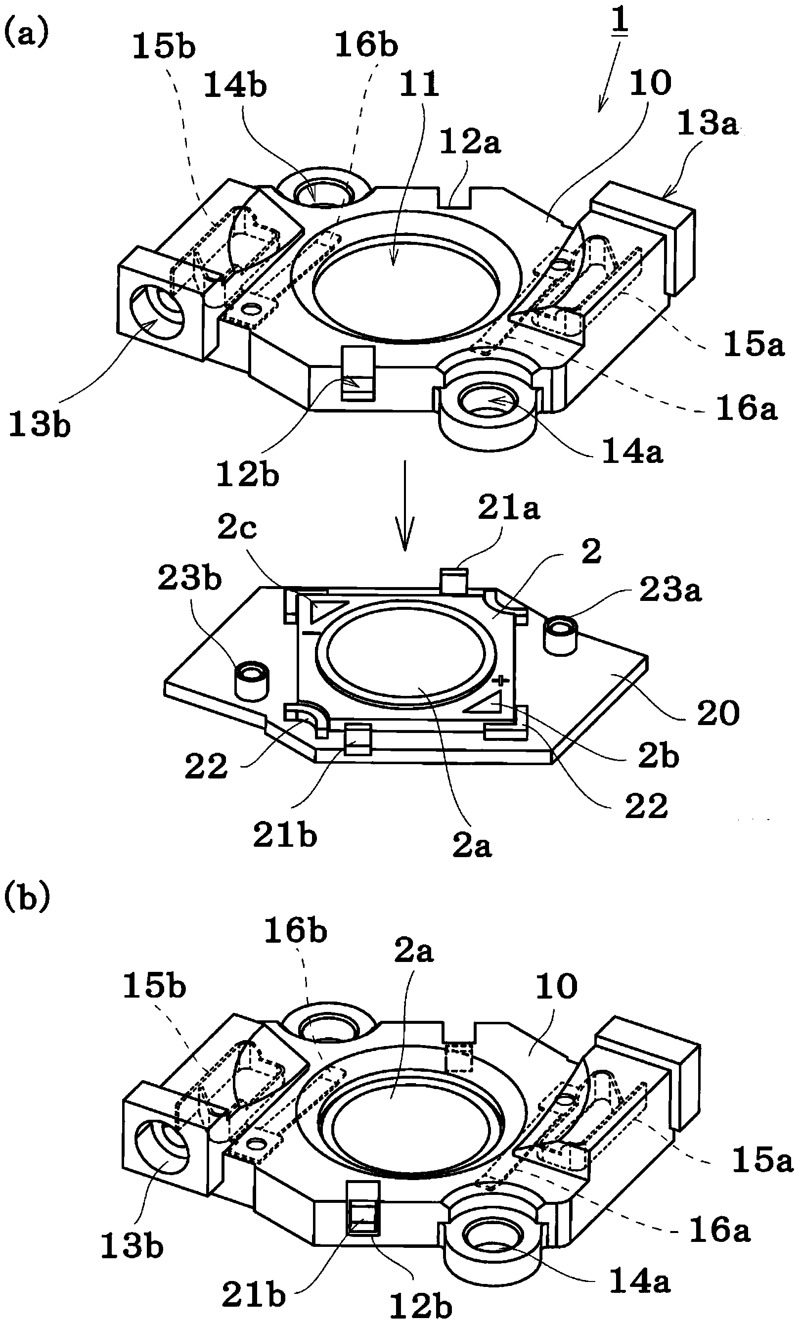
[0052] Next, a configuration example of a connector for an LED module substrate (hereinafter simply referred to as a “connector”) 1 according to the present invention will be described with reference to the drawings.

[0053] In the following embodiments, although various limitations are made on constituent elements, types, combinations, shapes, relative arrangements, etc., these are merely examples, and the present invention is not limited thereto.

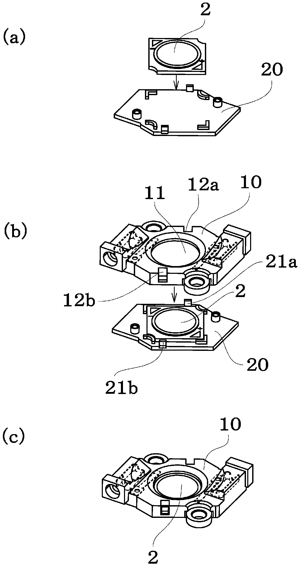
[0054] figure 1 represents the first embodiment, figure 2 Indicates the assembly sequence.

[0055] The lower cover member 20 is molded from a thermally conductive insulating resin material having a thermal conductivity (steady state method) of 1.5 W / mK or higher, preferably 5.0 W / mK or higher, and a dielectric breakdown voltage of Insulation above 1KV.

[0056] In an embodiment of the present invention, at least the portion of the lower cover member 20 located on the bottom surface of the LED module substrate is formed of t...


PUM


Abstract

There is provided a connector for an LED module board excellent in assembly, heat dissipation and insulation. The connector for an LED module board for holding and electrically connecting the LED module board includes: a lower cover member on which the LED module board is placed; and an upper cover member having a connection terminal brought into elastic contact with a power supply pad included in the LED module board, wherein at least a portion of the lower cover member at a position of a bottom face of the LED module board is made of a thermally-conductive and insulating material, the upper cover member is structured so that light emitted from the LED module board is directed outward, and the upper cover member is engaged with the lower cover member in a state in which the LED module board is placed on the lower cover member.

Description

technical field [0001] The invention relates to a connector for the electrical connection of a chip-on-board type LED module substrate. Background technique [0002] COB (chip on board) type LED module substrates in which LED elements are mounted on substrates are used in lighting and other fields. [0003] Such an LED module substrate must dissipate heat generated from the LED element to the outside. [0004] Then, for example Figure 10 As shown, in the past, the LED module substrate 2 is placed on the heat sink 3 for heat dissipation, and from above, using the cover member 110 having the connection terminal for power supply, it is mounted and fixed with mounting members 4a, 4b such as screws, and pressed. On the heat sink, the cables 5, 5 are connected to contacts provided on the cover part. [0005] However, in such an LED module substrate mounting method, the LED module substrate and the cover member as a connector must be mounted on the heat sink, respectively, and t...

Claims


Application Information

Patent Timeline
Patent Type & Authority Applications(China)
IPC IPC(8): H01R12/71H01L23/34H01R13/502
CPCH01L2924/0002F21Y2101/02F21V29/20F21V1/00F21V19/003H01R13/2442H01R13/7175H01L24/72F21Y2115/10F21V29/15F21V29/70F21V29/85H01R12/51H01L33/00H01R33/05
Inventor 田中克佳竹田利光
Owner SMK CO LTD
Why Eureka
Try Eureka