CT device and method thereof

A technology of equipment and electron guns, applied in X-ray equipment, diagnosis, application, etc., can solve the problem that ultra-high-speed scanning cannot be further realized

Active Publication Date: 2014-07-09
TSINGHUA UNIV +1
View PDF8 Cites 3 Cited by
  • Summary
  • Abstract
  • Description
  • Claims
  • Application Information

AI Technical Summary

Problems solved by technology

[0009] The above methods can speed up the scanning speed to a certain extent, but they cannot further realize ultra-high-speed scanning and tomographic imaging of high-speed moving objects

Method used


Image

  • CT device and method thereof
  • CT device and method thereof
  • CT device and method thereof

Examples


Embodiment Construction

[0035] Specific embodiments of the present technology will be described in detail below, and it should be noted that the embodiments described here are only used for illustration, and are not intended to limit the present technology. In the following description, numerous specific details are set forth in order to provide a thorough understanding of the technology. It will be apparent, however, to one of ordinary skill in the art that these specific details need not be employed to practice the present technology. In other instances, well-known structures, materials or methods have not been described in detail in order to avoid obscuring the present technology.

[0036] Throughout this specification, reference to "one embodiment," "an embodiment," "an example," or "an example" means that a particular feature, structure, or characteristic described in connection with the embodiment or example is included in the present technology. In at least one embodiment. Thus, appearances ...


PUM


Abstract

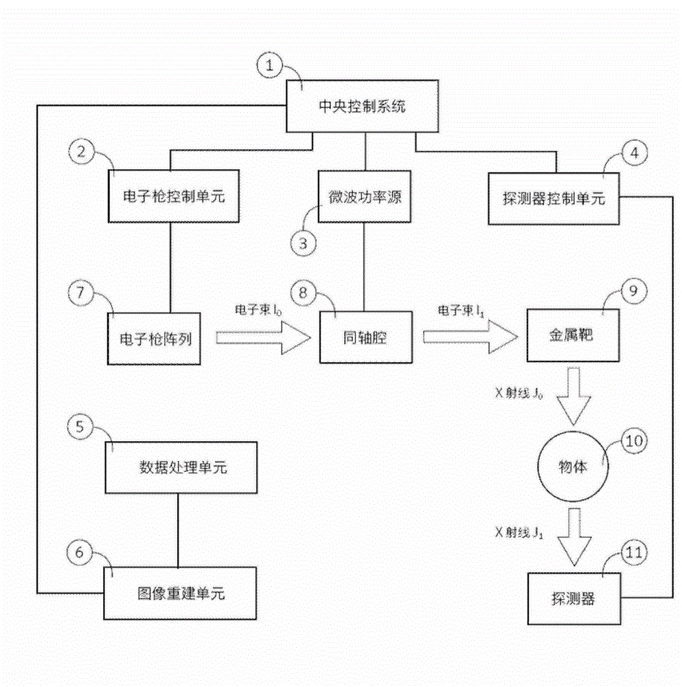
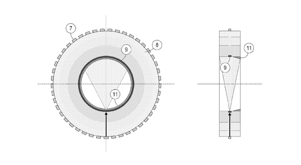
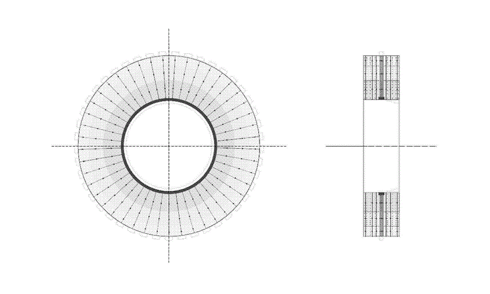
A CT device and a CT imaging method thereof. The CT device comprises: an annular electron gun array (7) that comprises multiple electron guns, wherein each electron gun is configured to emit an electron beam sequentially along a radial direction of the annular electron gun array (7) according to a predetermined pulse sequence; an accelerating cavity (8), which is arranged at an annular inner side of the annular electron gun array (7), comprises multiple concentric coaxial cavities that are embedded together, works in π mode and is used for sequentially accelerating the electron beam emitted by each electron gun of the annular electron gun array (7); an annular transmission target (9), which is arranged at an annular inner side of the accelerating cavity (8), and bombarded by the accelerated electron beam to generate an X-ray; and an annular detector (11), which receives the X-ray that penetrates an examined object.

Description

technical field [0001] The technology relates to medical imaging, industrial detection and other fields. It can be directly applied to medical applications that require ultra-high-speed imaging, and can also be used in industrial applications such as non-destructive testing. Background technique [0002] CT is the abbreviation of Computed Tomography, that is, computerized tomography technology, which is a scanning method that uses computer technology to reconstruct the tomographic image of the measured object to obtain a three-dimensional tomographic image. The scanning method is to penetrate the measured object through the rays of a single axis, and according to the different absorption and transmittance of each part of the measured object, the transmitted rays are collected by the computer and imaged through three-dimensional reconstruction. The CT mentioned in this patent refers to X-ray CT unless otherwise specified. [0003] According to the development, CT can be div...

Claims


Application Information

Patent Timeline
Patent Type & Authority Applications(China)
IPC IPC(8): A61B6/03G01N23/04
CPCG01N23/04H05G2/00H05H9/00H05H7/18G01N23/046A61B6/03A61B6/032A61B6/4028A61B6/4275G01N2223/419H01J35/116H05G1/10H05G1/32
Inventor 康克军唐传祥赵自然张哲
Owner TSINGHUA UNIV
Why Eureka
Try Eureka