
Micro-power sewage biological rapid filtration system and technology using the same

A sewage biological and micro-dynamic technology, applied in the direction of water/sewage multi-stage treatment, water/sludge/sewage treatment, chemical instruments and methods, etc. Changes, sewage treatment and discharge management problems such as inconvenience, to achieve the effect of beautifying the environment

Active Publication Date: 2014-07-09
卓勒(上海)环境工程有限公司
View PDF5 Cites 0 Cited by
  • Summary
  • Abstract
  • Description
  • Claims
  • Application Information

AI Technical Summary

Problems solved by technology

Although soil treatment can meet the technical requirements of the current "Pollutant Discharge Standards for Urban Sewage Treatment Plants" GB18918-2002, it requires a long residence time in water bodies and covers a large area. Since sewage mainly needs to be treated by soil infiltration, soil treatment The technology is greatly affected by the climate. During the rainy season, the soil absorbs a large amount of rainwater and is saturated. In winter, the soil surface freezes, affecting water infiltration and isolating the air. The activity of microorganisms in the soil will also decrease at low temperatures, which also leads to a reduction in sewage. Treatment efficiency, but the amount of sewage to be treated is not changed by climate change, which brings great inconvenience to the management of sewage treatment and discharge

Method used


Image

  • Micro-power sewage biological rapid filtration system and technology using the same
  • Micro-power sewage biological rapid filtration system and technology using the same
  • Micro-power sewage biological rapid filtration system and technology using the same

Examples


Embodiment Construction

[0046] Below we combine the accompanying drawings and specific examples to further describe this microdynamic sewage biological rapid filtration system and process in detail.

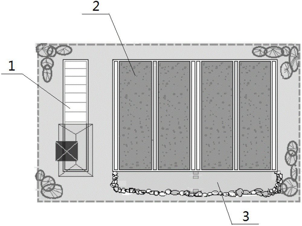
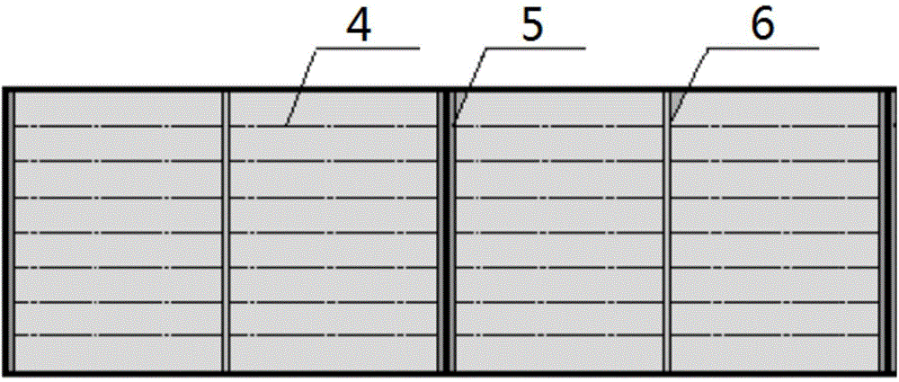
[0047] This microdynamic sewage biological fast filtration system includes a pretreatment pool 1, a program-controlled fast filter field 2 and a disinfection reaction pool 3 connected in sequence, and is characterized in that: the program-controlled fast filter field 2 includes the main body of the first fast filter field and The main body of the second quick filter field, the water inlet and air intake mechanism arranged at the center of the main body of the quick filter field, and the return mechanism symmetrically arranged on both sides of the main body of the quick filter field; Interconnected perforated return pipes 4; the main body of the quick filter field is filled with multiple functional filter material layers, and an anti-seepage film 7 is laid on the inner wall of the main body of the quick f...


PUM

PropertyMeasurementUnit
sizeaaaaaaaaaa
diameteraaaaaaaaaa
diameteraaaaaaaaaa

Abstract

The invention discloses a micro-power sewage biological rapid filtration system. The micro-power sewage biological rapid filtration system comprises a pretreatment tank, a program-controlled rapid filtration field and a disinfection reaction tank, and the pretreatment tank, the program-controlled rapid filtration field and the disinfection reaction tank are orderly connected. The program-controlled rapid filtration field comprises a first rapid filtration field main-body, a second rapid filtration field main-body, a water-inlet air-inlet mechanism arranged in the middle of each one of the rapid filtration field main-bodies and backflow mechanisms respectively arranged at two sides of each one of the rapid filtration field main-bodies. Communicated perforated overflow pipes are arranged between upper parts of the water-inlet air-inlet mechanisms and upper parts of the backflow mechanisms. The rapid filtration field main-bodies are filled with multiple functional filter material layers. The inner walls of the rapid filtration field main-bodies are coated with impermeable PE films. In aeration, through use of gas stripping effects produced in water inflation, water in the water-inlet air-inlet mechanisms automatically overflows and flows into the backflow mechanisms so that additional electricity consumption equipment for driving water circulation is avoided and an energy consumption cost of the system in use is further reduced.

Description

technical field [0001] The invention relates to a domestic sewage treatment system, in particular to a low-energy microdynamic sewage biological rapid filtration system and a process, which belong to the technical field of environmental protection and sewage treatment engineering. Background technique [0002] With the construction of "new countryside" and the rapid development of villas and recreational areas, a new type of decentralized small domestic sewage treatment facility has become the new favorite of the environmental protection market. Currently commonly used sewage treatment processes, such as biological filter, contact oxidation, SBR, and soil treatment, cannot well meet the special requirements of high standards, low energy consumption, low investment, free management, and less land occupation in this field for sewage treatment facilities. . [0003] Due to the short passing time of biological filter technology, the complete nitrification of ammonia nitrogen an...

Claims


Application Information

Patent Timeline
Patent Type & Authority Applications(China)
IPC IPC(8): C02F9/14
Inventor 王忠诚徐亚同马修·埃米特·拜尔斯李云宁纽特·家·郭
Owner 卓勒(上海)环境工程有限公司
Learn More