A method of improving the service life of the mud cannon nozzle of the blast furnace front equipment

A nozzle and equipment technology, applied in blast furnaces, blast furnace details, blast furnace parts, etc., can solve the problems affecting the tightness of the nozzle and the taphole, the roundness of the mud sleeve is not accurate enough, and the service life of the nozzle is discounted, etc. problems, to achieve the effect of reducing nozzle rupture, avoiding mud leakage and iron permeation, and prolonging the maintenance period

Active Publication Date: 2017-11-10
TANGSHAN CAOFEIDIAN DISTRICT SHOUYAN MACHINERY CO LTD
View PDF7 Cites 0 Cited by
  • Summary
  • Abstract
  • Description
  • Claims
  • Application Information

AI Technical Summary

Problems solved by technology

According to on-site observation, in the process of forming and compacting the mud sleeve, the original solid tamping mold generated wet mud splashing at the impact moment of tamping due to the poor exhaust of the wet mud, resulting in inaccurate local roundness of the mud sleeve and internal pass The surface is roughened, which affects the tightness of the nozzle and the tap hole when the mud gun is blocked, and causes the surrounding (mostly the lower end) of the nozzle to be burned due to mud leakage (leakage of molten iron). Therefore, the gun The service life of the nozzle is not only related to the nozzle structure and material structure, but also closely related to the production quality of the taphole bushing
[0005] At the same time, due to the unreasonable structure of the nozzle, it will also cause loose fit with the mud sleeve, resulting in leakage of molten iron, and then burn out the nozzle, greatly reducing the service life of the nozzle

Method used


Image

  • A method of improving the service life of the mud cannon nozzle of the blast furnace front equipment
  • A method of improving the service life of the mud cannon nozzle of the blast furnace front equipment
  • A method of improving the service life of the mud cannon nozzle of the blast furnace front equipment

Examples


Embodiment Construction

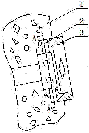
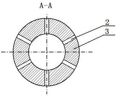
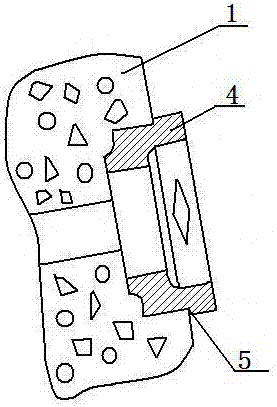
[0018] The parts and components indicated by the symbols in the accompanying drawings are as follows:

[0019] Mud sheath mold: mud sheath 1, vent hole 2, hollow cylinder 3; nozzle: cylindrical nozzle body 4, mouth step 5, pin hole 6, tangent plane 7.

[0020] The present invention will be further described below in conjunction with embodiment:

[0021] The present invention is a method for improving the service life of the mud cannon nozzle of the equipment in front of the blast furnace, including the improvement of the manufacturing method of the mud sheath and the improvement of the nozzle structure, and is characterized in that:

[0022] The manufacturing method of the mud jacket is improved as follows: use the mud jacket mold to open the mud jacket mold with air holes on the surface, and make it from refractory materials or ramming materials through three steps of mud stacking, compaction molding, and drying and curing;

[0023] The improved nozzle structure is as follow...


PUM


Abstract

The invention relates to a method for improving the service life of the mud cannon nozzle of the equipment in front of the blast furnace, which includes the improvement of the mud sheath manufacturing method and the nozzle structure improvement, and is characterized in that: the mud sheath manufacturing method is improved as follows: use the mud sheath mold to open the surface The mud sheath mold with air holes is made of refractory materials or ramming materials through three steps of mud stacking, compaction molding, and drying and curing; the improved nozzle structure is: the outer edge of the cylindrical nozzle body is equipped with Seam step, the cylindrical gun nozzle body on the outer edge of the seam step has all planes, and the tangent plane is provided with pin holes. The beneficial effect that can be achieved is to effectively improve the cylindricity and surface finish of the mud sleeve, ensure that the inner cavity of the mud sleeve is closely attached to the working surface of the nozzle, avoid mud leakage and iron seepage, and greatly reduce the probability of burnout of the nozzle end surface. The increase of the mouth step can not only effectively increase the overall bonding area of ​​the nozzle to avoid mud leakage, but also improve the compression and impact resistance when the mouth is blocked to reduce the rupture of the nozzle.

Description

technical field [0001] The invention relates to a mud cannon nozzle of a steelmaking blast furnace, which belongs to the technical field of metallurgy, in particular to a method for improving the service life of the mud cannon nozzle of a blast furnace front equipment. Background technique [0002] The blast furnace front equipment mud cannon nozzle is a relatively large consumption of vulnerable parts in the ironmaking furnace front equipment, and occupies a certain proportion in the cost calculation of the use and maintenance of the front furnace equipment. When the mud cannon blocks the blast furnace taphole, the nozzle is in direct contact with the hot molten iron, and it is easily ablated due to the erosion of the molten iron. Generally, one nozzle is burnt once the iron is tapped. Therefore, the nozzle of the mud cannon in the blast furnace workshop is easy to burn. Damaged parts, its consumption and equipment maintenance workload are quite large. [0003] The main re...

Claims


Application Information

Patent Timeline
Patent Type & Authority Patents(China)
IPC IPC(8): C21B7/12
Inventor 陈旭荣
Owner TANGSHAN CAOFEIDIAN DISTRICT SHOUYAN MACHINERY CO LTD
Why Eureka
Try Eureka