
Compact false twist spindle device with novel structure

A compact and new structure technology, applied in textiles and papermaking, etc., can solve the problems of high production capacity and energy consumption, and affect the quality of false twisted textured yarn, so as to achieve high production capacity, increase spindle density and improve quality

Inactive Publication Date: 2014-07-09
JIANGSU HAIYUAN MACHINERY
View PDF6 Cites 1 Cited by
  • Summary
  • Abstract
  • Description
  • Claims
  • Application Information

AI Technical Summary

Problems solved by technology

[0003] The center distance of each section of the existing false twist texturing machine is 1440mm. Since the false twist spindle gauge width is 110mm, each section is divided into A and B sides, and each section can only install 24 false twisters for 24 yarns. False twisting, so productivity and energy consumption are relatively high
At the same time, due to the vibration of the machine, the bearing cannot keep a good contact with the dragon belt when the spindle shaft of the false twister is driven by the friction force to rotate at a high speed, which directly affects the quality of the false twist textured yarn.

Method used


Image

  • Compact false twist spindle device with novel structure
  • Compact false twist spindle device with novel structure
  • Compact false twist spindle device with novel structure

Examples


Embodiment Construction

[0018] The present invention will be further described below in conjunction with accompanying drawing:

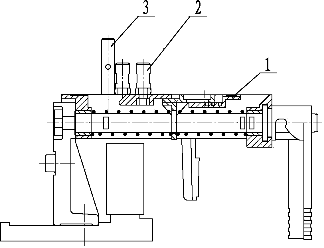
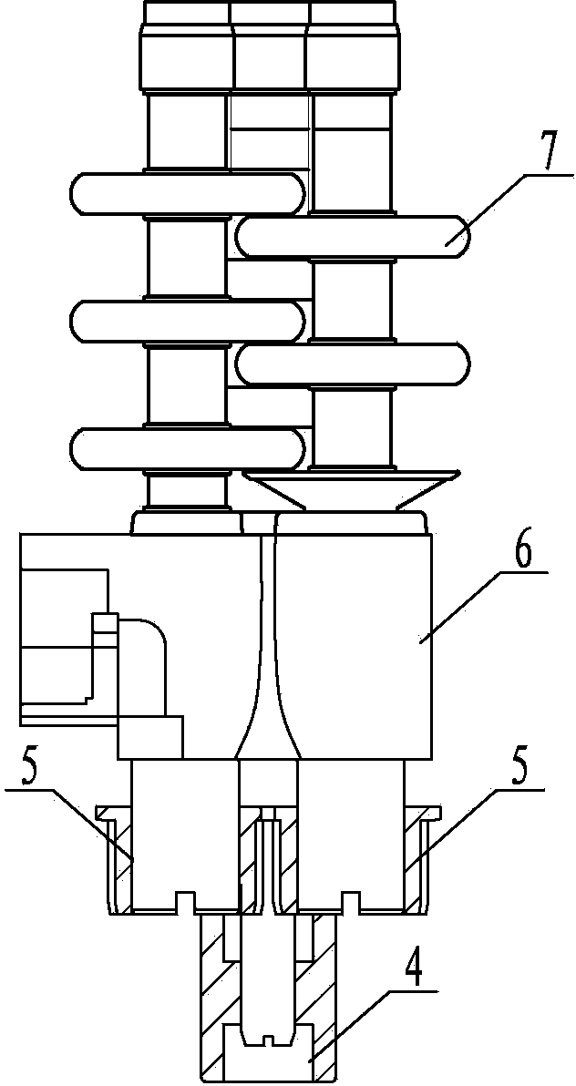
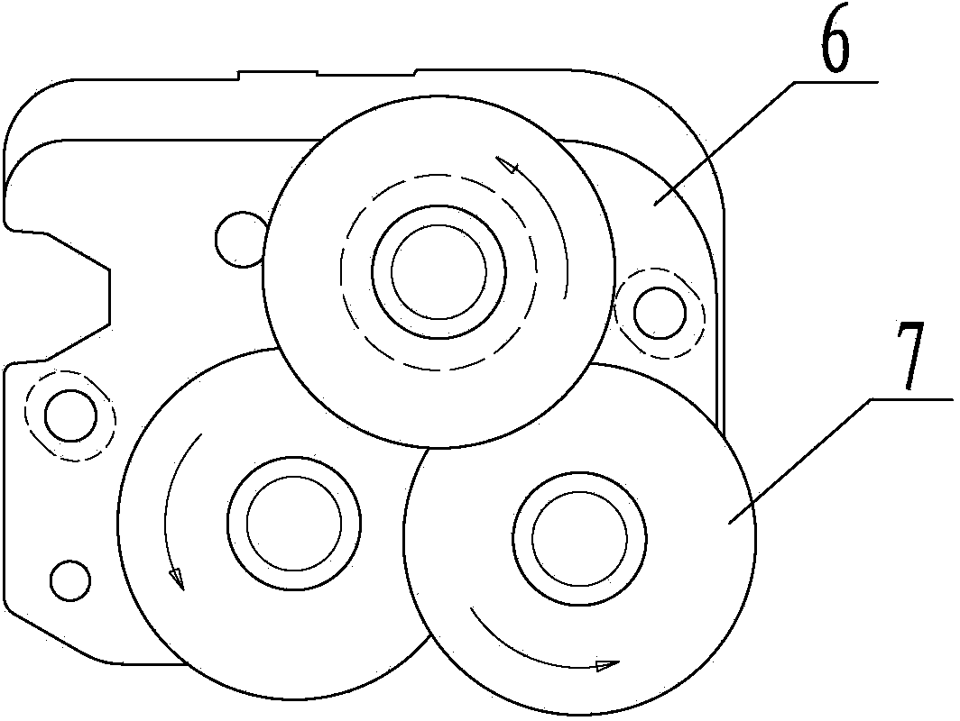
[0019] as attached figure 1 As shown in -7, the present invention includes a seat body 6 on the upper part of the false twister. Two driven bearings 5 ​​and a driving bearing 4 are installed on the seat body 6. The center distances of their three spindle shafts form a triangle , the friction discs 7 superimposed on each other in a certain order at the center of the triangle are installed on the three spindle shafts, the driving bearing 5 and the driven bearing 4 are connected by a synchronous toothed belt, and the three spindles are connected by the toothed belt. The friction discs 7 on the shaft rotate in the same direction. The base body 6 is installed on the lower part of the false twister through a spindle position pin 3 and two fixed pins 2, and the bracket joint 1 at the lower part of the false twister adopts a lateral groove (such as Figure 8 As shown), the bracke...


PUM

PropertyMeasurementUnit
widthaaaaaaaaaa

Abstract

The invention discloses a compact false twist spindle device with a novel structure. The compact false twist spindle device is characterized by comprising a seat (6), the seat is positioned on the upper portion of a false twister, two driven bearings (5) and a driving bearing (4) are mounted on the seat (6), axial distances of three spindle axes of the bearings form a triangle, friction discs (7) which are overlaid on one another in the center of the triangle according to a certain sequence are mounted on the three spindle axes, the seat (6) is mounted on the lower portion of the false twister via a spindle position pin (3) and two fixing pins (2), and grooves are laterally formed in a support connector (1) on the lower portion of the false twister. The compact false twist spindle device has the advantages that spindle position structures are changed on the basis of the original false high-speed stretch yarn machine, the spindle density can be increased, and multi-spindle-position (32-spindle) and high-capacity effects can be realized; the grooves are laterally formed in the support connector instead of being downwardly formed originally, so that excellent contact stability of bearings of the false twister and tangential belts can be kept, and the quality of falsely twisted textured yarns can be improved.

Description

technical field [0001] The invention relates to a textile machine component of chemical fiber yarn, in particular to a false twist spindle structure. Background technique [0002] At present, most of the raw materials of chemical fiber filaments are false twisted and deformed by false twist texturing machines to obtain fluffy and elastic properties before entering the next process. Each twister is equipped with three spindle shafts, one driving shaft and two driven shafts. The center distance of the three spindle shafts forms a triangle, and the friction discs on the three shafts are superimposed on each other in a certain order at the center of the triangle. , the driving shaft and the driven shaft are connected by a synchronous toothed belt, and the toothed belt makes the friction discs on the three spindles rotate in the same direction. After being controlled by the frequency converter and two frequency conversion motors, the one-stop belt is driven, so that a fake The t...

Claims


Application Information

Patent Timeline
Patent Type & Authority Applications(China)
IPC IPC(8): D01H7/92
Inventor 王兆海
Owner JIANGSU HAIYUAN MACHINERY
Learn More