
Three-level DC converter output capacitor voltage equalization control system and its control method

A technology of DC converters and output capacitors, applied in the field of DC converters and DC converter output capacitor voltage equalizing devices, can solve problems such as unsatisfactory dynamic performance, inability to solve mid-point potential, difficulty in dealing with sudden changes in power, etc. The effect of reducing the voltage margin, reducing the distortion, and improving the reliability

Active Publication Date: 2017-01-11
YANGZHOU XINHONG ELECTRONICS
View PDF6 Cites 0 Cited by
  • Summary
  • Abstract
  • Description
  • Claims
  • Application Information

AI Technical Summary

Problems solved by technology

However, when the grid-connected inverter is started, the back-stage inverter circuit is not working, so this method cannot solve the problem of unbalanced midpoint potential during the start-up process.
[0004] The second is to use the table look-up method to determine the on and off of the upper and lower switch tubes according to the change of the voltage of the upper and lower capacitors on the DC side of the output DC side of the three-level Boost DC converter, so as to achieve the balance of the voltages of the two capacitors on the DC side , this method is relatively simple, but the dynamic performance is not very ideal
However, due to a large number of parasitic parameters in the actual circuit, as well as factors such as asymmetric capacitance parameters and sudden power changes, the parameters of the PI regulator need to be adjusted repeatedly, and a set of adjusted PI parameters is difficult to cope with sudden power changes.

Method used


Image

  • Three-level DC converter output capacitor voltage equalization control system and its control method
  • Three-level DC converter output capacitor voltage equalization control system and its control method
  • Three-level DC converter output capacitor voltage equalization control system and its control method

Examples


Embodiment Construction

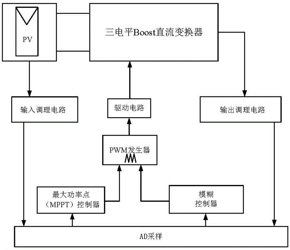
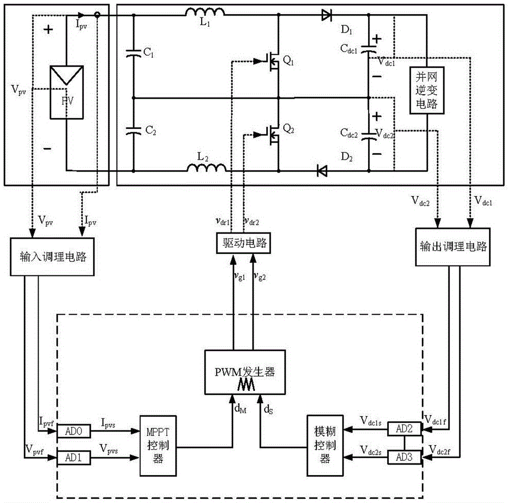
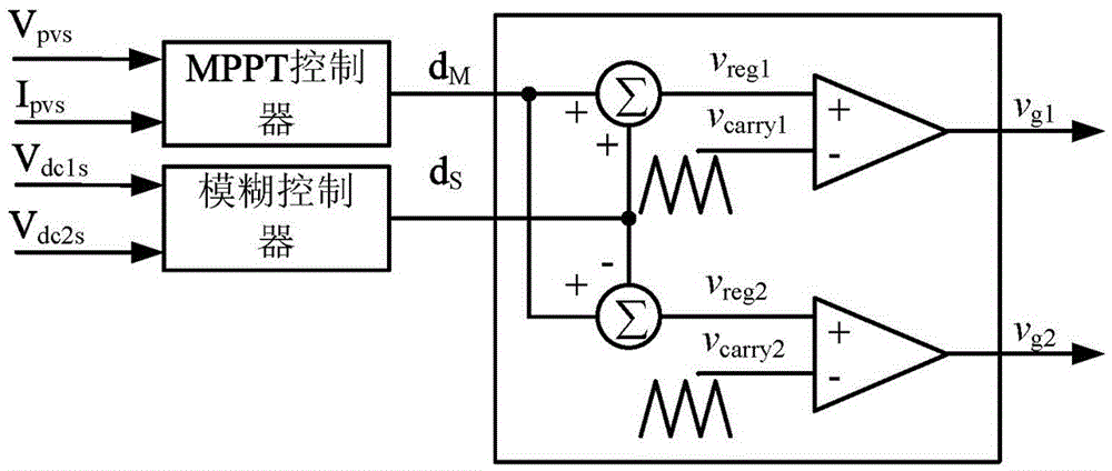
[0033] like figure 1 , figure 2 and image 3 As shown, the present invention includes: three-level Boost DC converter, drive circuit, input conditioning circuit, output conditioning circuit, AD sampling unit, PWM generator, MPPT controller, fuzzy controller, PV analog power supply, digital control chip, Among them, the AD sampling unit, PWM generator, MPPT controller and fuzzy controller are realized by software programming in the digital control chip, that is, digital control strategy.

[0034] The input voltage V of the three-level Boost DC converter pv and the input current signal I pv The signal quantity V is obtained through the input conditioning circuit pvf and I pvf Sent to the AD sampling unit, the obtained sampling value V pvs and I pvs As the input of MPPT controller 7; output capacitor voltage signal V dc1 and V dc2 The signal quantity V is obtained through the output conditioning circuit dc1f and V dc2f Sent to the AD sampling unit, the obtained sampli...


PUM


Abstract

The invention discloses a three-level DC converter output capacitor voltage equalization control system and its control method in the field of electronic engineering, including a PV analog power supply for the Boost DC converter, and the voltage and current signals at the input end of the Boost DC converter are sent to the input Conditioning circuit, the voltage signal at the output terminal of the Boost DC converter is sent to the output conditioning circuit, the signal output terminal of the input conditioning circuit, and the signal output terminal of the output conditioning circuit are connected to the signal input terminal of the digital signal processor, and the signal of the digital signal processor The output end is connected with a drive circuit, which controls the switching of the power tube in the Boost DC converter. The present invention can eliminate the midpoint unbalance problem caused by the inconsistency of the modulation strategy, the parameters of the circuit itself, and the drive delay. When the present invention is applied to When used in a two-stage non-isolated grid-connected power generation device, it can ensure the power generation quality of the rear-stage inverter.

Description

technical field [0001] The invention relates to a DC converter, in particular to a voltage equalizing device for output capacitors of the DC converter, and belongs to the technical field of electronic engineering. Background technique [0002] Before the present invention, in the two-stage non-isolated three-level grid-connected power generation device, the existing three-level Boost DC converter output capacitor voltage equalization control methods mainly include the following: [0003] One is the method of realizing midpoint potential balance through the inverter side: mainly by improving the modulation strategy of the inverter and the corresponding control method to achieve midpoint potential balance. However, when the grid-connected inverter is started, the back-stage inverter circuit is not working yet, so this method cannot solve the problem of unbalanced midpoint potential during the start-up process. [0004] The second is to use the table look-up method to determin...

Claims


Application Information

Patent Timeline
Patent Type & Authority Patents(China)
IPC IPC(8): H02M3/07
Inventor 方宇
Owner YANGZHOU XINHONG ELECTRONICS
Learn More