
Air dust collection equipment and air purifying device comprising same

A technology of air purification device and dust collection equipment, which is applied in the direction of electrode conveying device, external electrostatic separator, electrode structure, etc., which can solve the problems of dielectric strength drop, electrode breakdown, filter unusable, etc., and achieve creepage distance Effect of increasing, enhancing charge retention, reducing the risk of electrode breakdown

Inactive Publication Date: 2014-07-16
吴镇海 +2
View PDF6 Cites 4 Cited by
  • Summary
  • Abstract
  • Description
  • Claims
  • Application Information

AI Technical Summary

Problems solved by technology

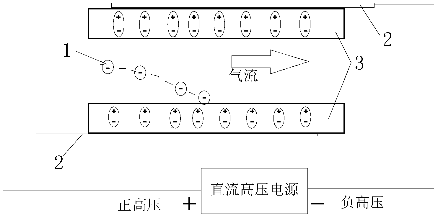
[0004] 1. When the external electric field stops power supply, the potential energy in the electret will also migrate back to the circuit loop or the ground due to the internal free space charge through the conductive material device, resulting in a decrease in the internal polarization electric field strength and weakening the adsorption of particles ability
[0005] 2. When the surface of the electret material is in a high-humidity environment, the dielectric strength of the material will also decrease due to the moisture absorption of the plastic material, especially if there are micropores on the surface of the plastic material at this time, direct contact with the plastic material The electrodes on the surface are more likely to cause electrode breakdown under the action of high voltage
[0007] 4. The air dust collection equipment made of conductive material directly in contact with the surface of the plastic material as the electrode, when it is not completely dried after washing, or in a high humidity environment (RH95%), or in the case of condensation, the plastic wall due to the material The moisture absorption causes a large drop in volume resistance, which can easily cause sparks between electrodes
At the same time, the space charge and dipole charge in the electret will disappear sharply, and the performance of the air dust collection equipment will decline. At the same time, in order to avoid breakdown, high voltage cannot be applied, and the filter screen is basically unusable at this time.

Method used


Image

  • Air dust collection equipment and air purifying device comprising same
  • Air dust collection equipment and air purifying device comprising same
  • Air dust collection equipment and air purifying device comprising same

Examples


Embodiment 1

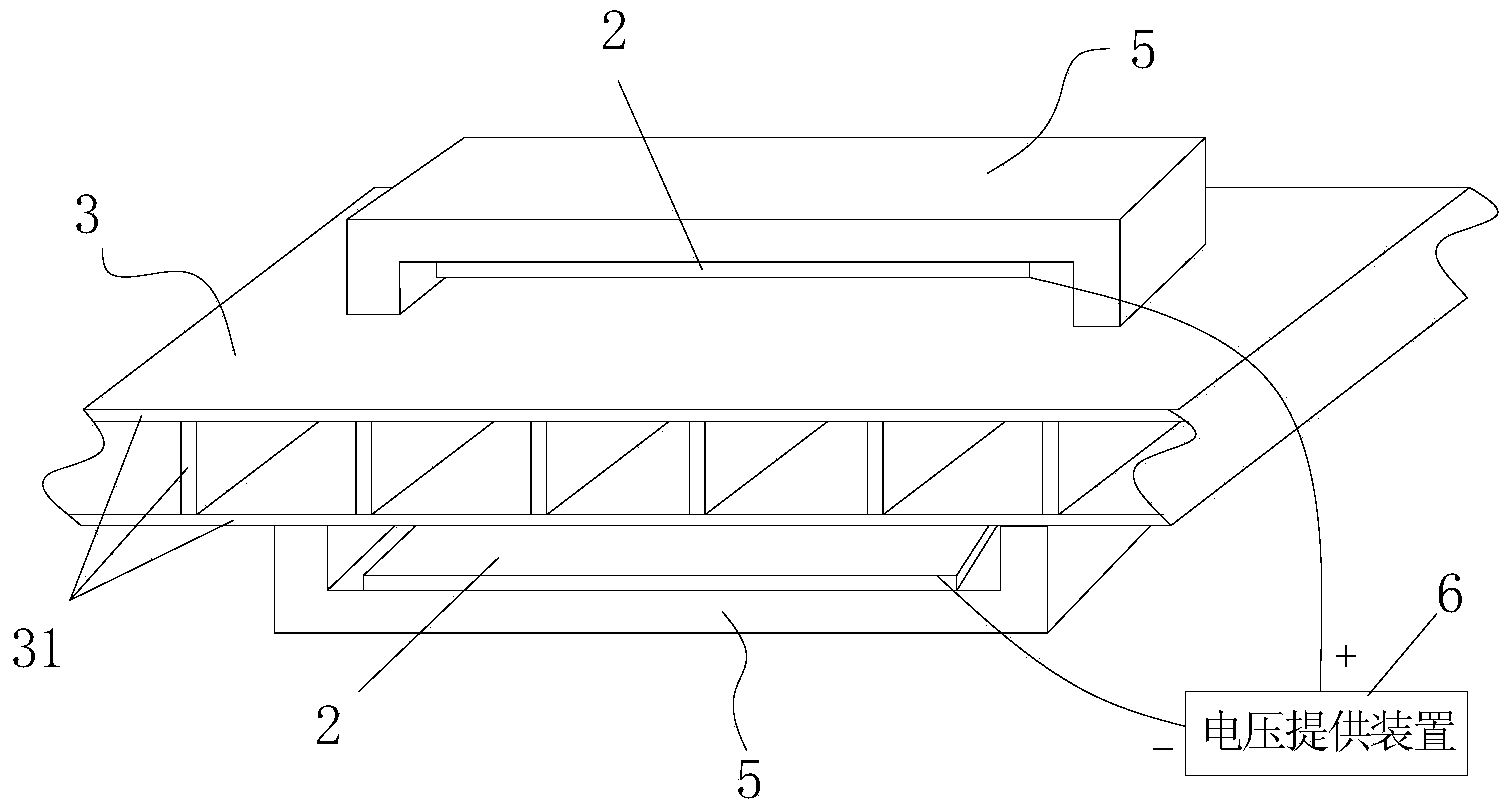
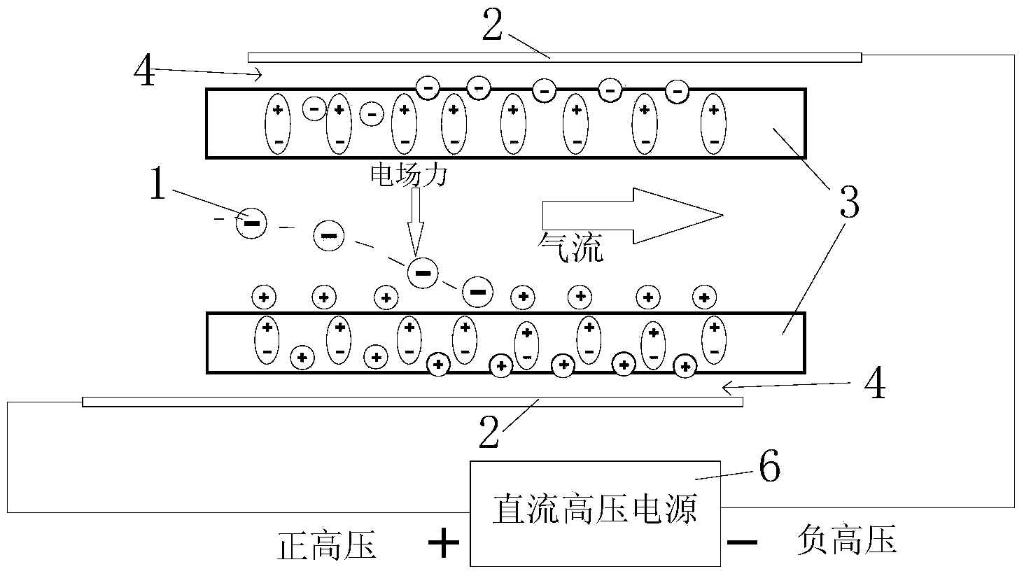
[0044] Such as figure 2 and image 3As shown, the air dust collection equipment of this embodiment includes a dust collection plate 3 surrounded by plates with more than one dust collection channel for air to pass through, an electrode bracket 5 arranged on the surface of the dust collection plate, and an electrode bracket 5 arranged on the surface of the dust collection plate. The conductive material layer 2 forming an air gap 4 between the electrode support 5 and the dust collecting plate 3 , and a voltage supply device 6 electrically connected to the conductive material layer are composed.

[0045] image 3 The middle airflow flows from the left side to the right side of the dust collection channel, where the electrode bracket is not drawn. In the figure, the lower conductive material layer is connected to the positive high-voltage output terminal of the DC high-voltage power supply, and the upper conductive material layer is connected to the negative high-voltage output...

Embodiment 2

[0049] The difference between this embodiment and the first embodiment is that it further includes an air driving device for driving air to pass through the dust collection channel. The air-driven device can be a blowing fan arranged at one end of the dust collection passage, or a suction fan. Through the function of the fan, the air can be quickly and effectively pushed to the dust collection channel, so as to accelerate the purification of charged particles in the air.

Embodiment 3

[0051] This embodiment is improved on the basis of embodiment one or two. Such as image 3 As shown, each electrode support 5 in this embodiment includes two support feet 51 and a support plate 52 . The support plate 52 is a long plate structure, its area is larger than the surface area of ​​the conductive material layer 2, its two ends are respectively connected to the middle of the support foot 51, and the entire electrode support 5 forms a symmetrical structure along the plane of the support plate. Since the electrode bracket is arranged between the two dust-collecting passages, its bracket feet are respectively in contact with the adjacent dust-collecting plates, and the conductive material layer is closely attached to the two planes of the bracket plate 52 . The conductive material layer 2 on the two planes of the support plate 52 may be in a conducting state or in an insulating state. When the material of the support plate 52 is a metal material, the two conductive mat...


PUM


Abstract

The invention relates to air dust collection equipment and an air purifying device. The air dust collection equipment comprises dust collecting plates, electrode supports, conducting material layers and a voltage providing device, wherein the dust collecting plates are surrounded by plates and are provided with more than one dust collecting channel, and the electrode supports and the outer surfaces of the dust collecting plate form air gaps; the conducting material layers are arranged on the electrode supports and are arranged opposite to the dust collecting plates through the air gaps, and more than one dust collecting plate is arranged between the two adjacent electrode supports; the voltage providing device respectively applies high potential and low potential to the conducting material layers on the two adjacent electrode supports so as to cause the dust collecting plates to adsorb air-charged particles in the dust collecting channels between the two adjacent electrode supports. The dust collecting plates cannot be conductive with a circuit loop or the ground as the air gaps and the conducting material layers are insulated. At the time of electrode without electricity, the polarization electric field of the dust collecting plates can still be maintained for a long time. Meanwhile, the creep age distance between the two adjacent electrodes is increased, therefore the risk that the electrodes are broken down is reduced, and the electrodes can quickly be dried after washing.

Description

technical field [0001] The invention relates to the technical field of air purification, in particular to an air dust collection device and an air purification device comprising the air dust collection device. Background technique [0002] Existing air cleaners have achieved electrostatic dust removal. For example, the patent No. ZL00806175.0, the patent of the invention titled air purification equipment, uses plastic array channels, conductive materials arranged on the surface of the array channels, high and low potential output devices interlaced with conductive materials, and devices that provide wind flow. The air purification device can effectively absorb the charged particles passing through the channels of the plastic array. [0003] When using plastic materials with electret characteristics as air dust collection equipment to collect charged particles in the air, in order to improve efficiency, it is necessary to use the high and low potential output devices that co...

Claims


Application Information

Patent Timeline
Patent Type & Authority Applications(China)
IPC IPC(8): B03C3/16B03C3/40B03C3/47B03C3/86B03C3/34
Inventor 郎欢标刘广胜孙茂华
Owner 吴镇海
Learn More