
Technological cylinder cover for machining cylinder holes of engine cylinder body and machining method therefor

A technology for engine cylinders and cylinder heads, which is applied in metal processing equipment, manufacturing tools, drilling/drilling equipment, etc., can solve the problems of shortened engine life, reduced sealing performance, uncontrollable wear, etc., and achieves less lubricating oil consumption, The inner wall is smooth and the effect of reducing sliding frictional resistance

Active Publication Date: 2014-07-16
CHONGQING CHANGAN AUTOMOBILE CO LTD
View PDF6 Cites 8 Cited by
  • Summary
  • Abstract
  • Description
  • Claims
  • Application Information

AI Technical Summary

Problems solved by technology

When assembling the cylinder head of the engine, the cylinder head screws must be tightened. At this time, the cylinder hole will be deformed and out of round. Fuel consumption increases. If the deformation is too large, the piston ring will also wear through the anti-wear coating on the inner wall of the cylinder bore. At this time, the wear will be uncontrollable, which will seriously shorten the life of the engine.

Method used


Image

  • Technological cylinder cover for machining cylinder holes of engine cylinder body and machining method therefor
  • Technological cylinder cover for machining cylinder holes of engine cylinder body and machining method therefor
  • Technological cylinder cover for machining cylinder holes of engine cylinder body and machining method therefor

Examples


Embodiment Construction

[0018] Further illustrate structure of the present invention below in conjunction with accompanying drawing:

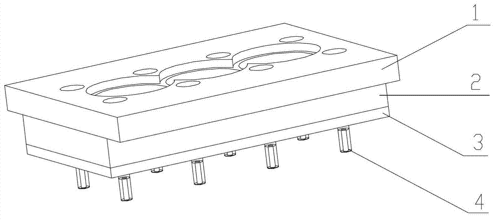
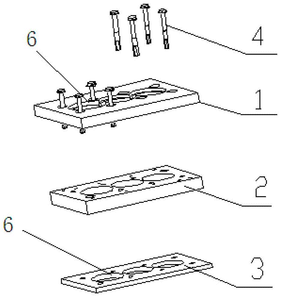
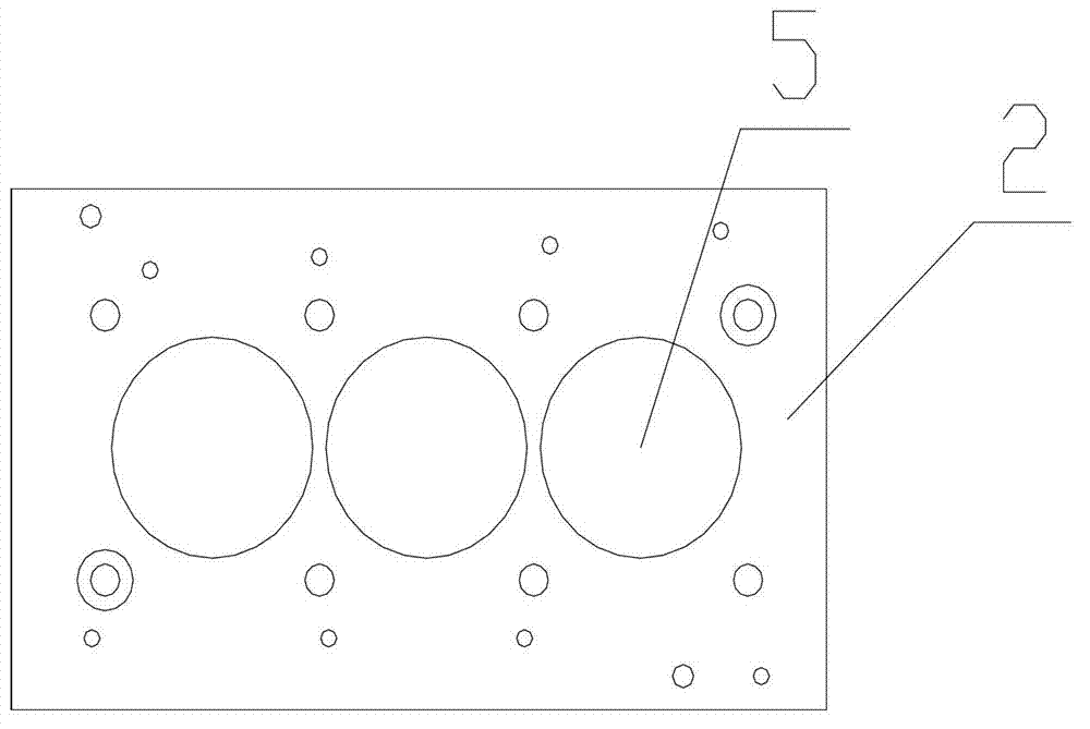
[0019] see figure 1 , the process cylinder head is formed by bolting the upper layer 1 of the process cylinder head, the middle layer 2 of the process cylinder head and the bottom layer 3 of the process cylinder head. The middle layer 2 of the process cylinder head adopts the same aluminum alloy plate as the material of the simulated cylinder head, and there is a hole 5 having the same diameter as the cylinder hole of the processed cylinder body on it. The upper layer 1 of the process cylinder head and the bottom layer 3 of the process cylinder head are made of steel plates, and they are provided with process through holes 6 at positions corresponding to the holes on the middle layer of the process cylinder cover.

[0020] When processing the engine cylinder bore, use bolts 4 to combine the upper layer 1 of the process cylinder head, the middle layer 2 of the process...


PUM


Abstract

The invention provides a technological cylinder cover for machining cylinder holes of an engine cylinder body; the technological cylinder cover is composed of an upper layer, a middle layer and a bottom layer connected through bolts, wherein the middle layer of the technological cylinder cover is made of aluminum alloy plates which have same texture with a cylinder cover to be simulated, holes of which the diameters are the same as these of the cylinder holes to be machined in the cylinder body are formed in the middle layer of the technological cylinder cover, the cylinder cover deformation can be simulated by CAE computation, and thus the actual cylinder cover can be simulated. The upper layer and the bottom layer of the technological cylinder cover are made of steel plates so as to reduce accumulated deformation and wearing of the technological cylinder cover caused by repeated use, technological holes corresponding to the cylinder holes in the middle layer of the technological cylinder cover are formed in the upper layer and the bottom layer of the technological cylinder cover. By using the technological cylinder to machine the cylinder holes, the cylinder holes distort as less as possible or hardly distort after the engine cylinder cover is installed, and thus the friction resistance between a piston ring and the cylinder hole wall is reduced, the run-in wear and oil consumption are decreased, the sealing property is improved, and the service life of the engine is prolonged.

Description

technical field [0001] The invention relates to engine processing, in particular to the processing of engine cylinder bores. Background technique [0002] Ordinary engines are processed separately from the cylinder bore and the cylinder head. When assembling the cylinder head of the engine, the cylinder head screws must be tightened. At this time, the cylinder hole will be deformed and out of round. Fuel consumption increases. If the amount of deformation is too large, the piston ring will also wear through the anti-wear coating on the inner wall of the cylinder bore. At this time, the wear will be uncontrollable and the life of the engine will be severely shortened. Contents of the invention [0003] The object of the present invention is to provide a process cylinder head and a processing method for processing the cylinder bore of the engine cylinder block to solve the above-mentioned problems, that is, to make the cylinder bore be out of round as little as possible or ...

Claims


Application Information

Patent Timeline
IPC IPC(8): B23B47/00B23B35/00
CPCB23B35/00B23B47/00
Inventor 夏新球邱阳何海珠
Owner CHONGQING CHANGAN AUTOMOBILE CO LTD
Learn More