Combined Brake Camshaft Laser Induction Composite Welding Method
A laser induction and composite welding technology, which is applied in laser welding equipment, welding equipment, metal processing equipment, etc., can solve the problems of inability to meet flexible production and high cost of friction welding equipment, and achieve the elimination of stress concentration and hardened martensite Organization, efficient use of energy, and reduced temperature gradient effects
- Summary
- Abstract
- Description
- Claims
- Application Information
AI Technical Summary
Problems solved by technology
Method used
Image

Examples
Embodiment 1
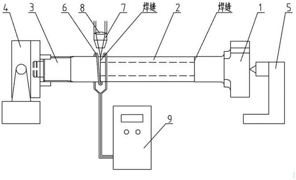
[0030] After assembling the cam 1, the hollow steel pipe shaft body 2 and the spline shaft 3 into a combined brake camshaft, place it horizontally, and position the two ends with the rotary three-jaw chuck 4 and the top 5 respectively. The inductor 6 is moved to the area to be welded, and cooling water is passed inside to ensure that the area is evenly heated at the same time, and the inner circumference of the inductor 6 is 3 cm away from the surface of the workpiece. Fix the laser welding head 7, focus the laser beam on the welding area, and rotate the three-jaw chuck 4 to drive the combined brake camshaft to rotate. At this time, the welding speed is 2m / min. The heating time of the inductor 6 is 5s, and the maximum heating temperature is 500°C. Laser welding starts at the end of heating, the laser welding power is 2000W, and the defocus is 0mm. He gas and compressed air are used to protect the welding pool and optical components during the welding process, and the gas flow ...
Embodiment 2
[0032] After assembling the cam 1, the hollow steel pipe shaft body 2 and the spline shaft 3 into a combined brake camshaft, place it horizontally, and position the two ends with the three-jaw chuck 4 and the top 5 respectively. The inductor 6 is moved to the area to be welded, and cooling water is passed inside to ensure that the area is evenly heated at the same time. The distance between the inner circumference of the inductor 6 and the surface of the workpiece is 5cm. Fix the laser welding head 7, focus the laser beam on the welding area, and rotate the three-jaw chuck to drive the combined brake camshaft to rotate. At this time, the welding speed is 3m / min. The heating time of the inductor 6 is 10s, and the maximum heating temperature is 600°C. Laser welding starts at the end of heating. The laser welding power is 3000W, and the defocus is +1mm. Ar gas and compressed air are used to protect the welding pool and optical components during the welding process, and the gas fl...
Embodiment 3
[0034] After assembling the cam 1, the hollow steel pipe shaft body 2 and the spline shaft 3 into a combined brake camshaft, place it horizontally, and position the two ends with the three-jaw chuck 4 and the top 5 respectively. The inductor 6 is moved to the area to be welded, and cooling water is passed inside to ensure that the area is evenly heated at the same time. The distance between the inner circumference of the inductor 6 and the surface of the workpiece is 4cm. Fix the laser welding head 7, focus the laser beam on the welding area, and use the laser to drive the combined brake cam shaft to rotate on the cam 1 and the rotary three-jaw chuck. At this time, the welding speed is 2.5m / min. Inductor 6 is energized and heated for 7s, the maximum heating temperature is 550°C, and then laser welding starts, the laser welding power is 2500W, the defocusing distance is 0.5mm, and the N 2 Gas and compressed air protect the welding pool and optical components during the welding ...
PUM
 Abstract
Description
Claims
Application Information