Micro-airflow sand belt position detection device and control method for broadband sander

A wide-band sanding machine and detection device technology, which is applied to belt grinders, workpiece feed motion control, manufacturing tools, etc., can solve problems such as poor internal environment of the machine and affect the normal use of the machine, and achieve timely correction and detection. Sensitive effect

Active Publication Date: 2017-01-04
HANGZHOU XIANGSHENG ABRASIVE MACHINE MFG
View PDF6 Cites 0 Cited by
  • Summary
  • Abstract
  • Description
  • Claims
  • Application Information

AI Technical Summary

Problems solved by technology

Its disadvantages: the photoelectric switch is used to detect the position of the abrasive belt, and the output signal is sent to the control mechanism to realize the function. Since the sander is a high-efficiency grinding method, a large amount of abrasive debris is generated, and the internal environment of the machine is very poor. The photoelectric switch requires a relatively high detection environment, so abnormal shutdowns due to lens pollution often occur, seriously affecting the normal use of the machine

Method used


Image

  • Micro-airflow sand belt position detection device and control method for broadband sander
  • Micro-airflow sand belt position detection device and control method for broadband sander
  • Micro-airflow sand belt position detection device and control method for broadband sander

Examples


Embodiment 1

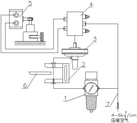
[0011] Embodiment 1: with reference to attached Figure 1-3 . A device for detecting the position of the micro-airflow abrasive belt of a wide-band sander. The compressed air pipeline 7 communicates with the inlet end of the reversing valve 4 through a three-way connection, and communicates with the inlet end of the blowing pressure regulating valve 1 through a three-way connection. The air outlet of the pressure valve 1 communicates with the air inlet of the small air hole in the air control board 2, and the air blown from the outlet of the air inlet end of the small air hole in the air control board 2 blows into the air inlet of the large air hole opposite to the small air hole in the air control board 2 Accept the airflow, the airflow at the air outlet end of the large hole communicates with the air inlet end of the air pressure amplifier 3 through the air circuit, and the air flow passes through the air pressure amplifier 3 to increase force and push the thimble to realize...

Embodiment 2

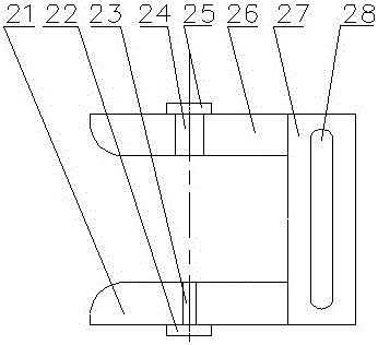
[0012] Embodiment 2: On the basis of Embodiment 1, a detection method of a micro-airflow sand belt position detection device of a wide-band sander, the compressed air gas delivery pipeline 7 inlet end leads to 4-6kg / cm 2 Compressed air, the compressed air is divided into two paths by the tee in the compressed air pipeline 7, one path directly enters the reversing valve 4, and the other path goes to the air blowing pressure regulating valve 1, and the compressed air passes through the air blowing pressure regulating valve 1 into the air Control board 2, the airflow blown out by blowing hole 23 in air control board 2 blows into the air connection hole 24 on the opposite side to receive the air flow, because the aperture of air blowing hole 23 is smaller than the diameter of air connection hole 24, the micro airflow received by air connection hole 24 flows in Air pressure amplifier 3, the air flow is amplified by the air pressure amplifier 3 to force the thimble in the air pressur...


PUM


Abstract

The invention relates to a device for detecting the position of a sanding belt of a wide belt sanding machine through micro air flow and a control method. According to the device, the micro air flow is adopted for detecting whether the sanding belt of the wide belt sanding machine deviates. A branch of a compressed air conveying pipeline is communicated with the air inlet end of a reversing valve through a tee joint, and a branch of the compressed air conveying pipeline is communicated with the air inlet end of an air blowing pressure-regulating valve. The air outlet end of the air blowing pressure-regulating valve is communicated with the air inlet end of a small air hole of an air control insertion plate, the outlet of the air inlet end of the small air hole of the air control insertion plate blows air flow, the air flow is blasted into the air control insertion plate, and a large air hole opposite to the small air hole receives the air flow. The air outlet end of the large air hole is communicated with the air inlet end of an air pressure amplifier through an air channel. The air flow is in switching cooperation with the control end of a reversing valve through a centre in the air pressure amplifier, and the two air outlet ends of the reversing valve are respectively communicated with the air inlet end of an oscillating cylinder. The device and control method have the advantage that the problem that due to the fact that a photoelectric detection head is polluted in the background technology, the disorderly closedown phenomenon of the sanding machine occurs frequently is solved fundamentally.

Description

technical field [0001] The invention relates to a micro-airflow belt position detection device and a control method for a belt of a wide-band sander that uses a micro-airflow to detect whether the belt of the wide-band sander is off-track. Background technique [0002] CN102814716A, titled "An automatic deviation correction mechanism for abrasive belts of polishing machines", including infrared sensors, DC servo motors, eccentric wheels, connecting rods, worm gear transmission mechanisms and deviation correction rollers; the infrared sensor, DC servo motor and worm gear transmission The mechanisms are all fixed on the bottom plate of the polishing machine; the deviation correcting roller is coaxially sleeved on the worm of the worm gear and worm transmission mechanism, and connected by a bearing, so that the deviation correction roller can rotate freely on the worm; the infrared sensor detects the running of the abrasive belt of the polishing machine. deviation, and transmit...

Claims


Application Information

Patent Timeline
Patent Type & Authority Patents(China)
IPC IPC(8): B24B21/20B24B49/00
CPCB24B21/20B24B49/00
Inventor 陈勇奇
Owner HANGZHOU XIANGSHENG ABRASIVE MACHINE MFG
Why Eureka
Try Eureka