Tire clamping mechanism for land leveller

A technology of clamping mechanism and grader, which is applied in the direction of workpiece clamping devices and manufacturing tools, can solve the problems of tire drop, large size and weight, and increase the working load of the telescopic end of lifting equipment, so as to reduce loss, The effect of increasing movement speed

Inactive Publication Date: 2014-07-16
CHENGDU HAILINGDA MACHINERY
View PDF4 Cites 4 Cited by
  • Summary
  • Abstract
  • Description
  • Claims
  • Application Information

AI Technical Summary

Problems solved by technology

[0003] In the production and assembly of motor graders, due to its large size and weight, it is generally difficult to manually move and assemble various parts
During the production, installation and disassembly process of motor grader tires, the ordinary peripheral clamping method is around the tire, and the outer ring of the tire is clamped by mechanical claws from the periphery to the middle to fix the tire. Although this clamping method can ensure that the tire It moves smoothly, but when the tire is vulcanized and other production and processing procedures, the peripheral clamping cannot meet the needs of production and processing; and in the ordinary peripheral clamping process, the mechanical jaw uses the hydraulic cylinder to clamp the tire, so that the clamping The overall weight of the head increases, which increases the working load of the telescopic end of the lifting equipment. During the clamping process, the hydraulic cylinder drives the mechanical claws to contact the tires for a rigid connection. Once the hydraulic cylinder fails, it is easy to make the clamped tire fall.

Method used


Image

  • Tire clamping mechanism for land leveller
  • Tire clamping mechanism for land leveller
  • Tire clamping mechanism for land leveller

Examples


Embodiment 1

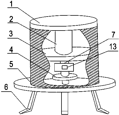
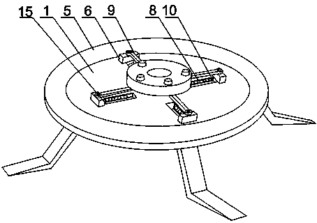
[0023] Such as Figure 1 to Figure 3 As shown, the motor grader tire clamping mechanism of the present invention includes a support cylinder 1, a baffle 3 is installed in the support cylinder 1, a motor 2 is fixedly arranged on the baffle 3, and the output end of the motor 2 passes through the baffle The plate 3 is connected with the turntable 4, and a plurality of horizontal grooves 15 are evenly arranged on the other end of the support cylinder 1, and claws are slidingly provided in the horizontal grooves 15; a connecting rod 9 is also included, and the connecting rod 9 One end is hinged with the turntable 4, the other end of the connecting rod 9 is hinged with the end of the claw, and a rectangular blind hole 10 is arranged on the inner wall of the horizontal groove 15, and a plurality of rollers 8 are installed in the rectangular blind hole 10; Position structure, the position-limiting structure is arranged on the baffle plate 3 . When the present invention works, put the...

Embodiment 2

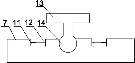
[0025] Such as figure 1 with image 3As shown, this embodiment is based on Embodiment 1, the limiting structure includes a limiting plate 7, the limiting plate 7 is fixed on the baffle plate 3, and a through hole is opened in the middle of the limiting plate 7 , the motor output end 14 passes through the through hole, two grooves 12 are opened on the same side of the limiting plate 7, and the two grooves 12 are located on both sides of the motor output end 14, on the motor output end 14 A T-shaped block 13 is installed, and a travel switch 11 is installed in the groove 12, and the travel switch 11 is connected to the motor 2 through a wire. When clamping the tire placed horizontally, the motor 2 rotates to drive the T-shaped block 13 on the output end 14 of the motor to rotate, and when the claw slides to the outermost end of the horizontal groove 15, one end of the T-shaped block 13 and The travel switch 11 in the groove 12 contacts, and the travel switch 11 controls the mo...

Embodiment 3

[0027] Such as figure 1 with figure 2 As shown, in this embodiment, on the basis of Embodiment 1, the claws include an L-shaped slider 6, and the end of the vertical part of the L-shaped slider 6 is slidably arranged in the horizontal groove 15, and the L-shaped slider The end face of the horizontal portion of the block 6 is an inclined face. The horizontal portion of the L-shaped slider 6 can provide good support for the tire, ensuring that the center of the tire is always on the axis of the support cylinder 1 during the clamping movement. A plurality of L-shaped sliders 6 form a slider circle. When sliding When the block ring is in the shrinking state, the L-shaped slider 6 and the hinged block at the end of the horizontal part of the L-shaped slider 6 move to the center position of the tire. Driven by the connecting rod 9, the slider ring expands outward rapidly, and finally The L-shaped slider 6 clamps the inner ring of the tire to prevent the center of gravity of the t...


PUM


Abstract

The invention discloses a tire clamping mechanism for a land leveller. The tire clamping mechanism comprises a supporting cylinder body, a connecting rod and a limiting structure. A baffle is installed in the supporting cylinder body and fixedly provided with a motor. The output end of the motor is connected with a rotating plate after penetrating through the baffle. A plurality of horizontal grooves are uniformly formed in the other end of the supporting cylinder body, and clamping claws are arranged in the horizontal grooves in a sliding mode. One end of the connecting rod is hinged to the bottom of the rotating plate, and the other end of the connecting rod is hinged to the end portions of the clamping claws. Rectangular blind holes are formed in the inner walls of the horizontal grooves, and a plurality of idler wheels are installed in the rectangular blind holes. The limiting structure is arranged on the baffle. The idler wheels in the horizontal grooves can change sliding friction between the clamping claws and the groove walls into rolling friction, loss between the horizontal grooves and the clamping claws can be reduced, and the moving speed of the clamping claws can be increased. In the rotating process, the motor rotates horizontally at a constant oscillation angle, and therefore the clamping claws can move in the horizontal grooves fast.

Description

technical field [0001] The invention relates to a clamping tool, in particular to a tire clamping mechanism of a motor grader. Background technique [0002] The grader is an earthmoving machine that uses a scraper to level the ground. It is suitable for building roadbeds and road surfaces, building side slopes, digging side ditches, mixing road surface mixtures, sweeping snow, pushing loose materials, and maintenance of dirt roads and gravel roads. Work. There are two types of motor graders: double-axis and three-axis. The commonly used one is three-axis. differential for steering. The working principle of the grader is roughly as follows: the scraper is installed under the slewing ring through two brackets, and the slewing ring can be rotated to adjust the position of the scraper; the bracket of the slewing ring is triangular, and its front end is hinged on the front of the main frame, and The two corners are suspended in the middle of the main frame by lifting hydraulic...

Claims


Application Information

Patent Timeline
Patent Type & Authority Applications(China)
IPC IPC(8): B25B11/00B25B11/02
CPCB25B11/00B25B11/02
Inventor 陈志强
Owner CHENGDU HAILINGDA MACHINERY
Why Eureka
Try Eureka