
Air overfeeding tube

A technology of feeding tube and air, which is applied in the direction of textiles and papermaking, etc. It can solve the problems of yarn damage caused by the rotation of the guide wheel, increase the hairiness of the yarn surface, reduce the strength of the yarn, etc., and achieve the effect of simple structure

Inactive Publication Date: 2014-07-16
WUJIANG MINGJIA WEAVING
View PDF4 Cites 2 Cited by
  • Summary
  • Abstract
  • Description
  • Claims
  • Application Information

AI Technical Summary

Problems solved by technology

[0002] In the prior art, the yarn overfeeding device mostly adopts the form that the guide wheel drives the yarn to move. This technical solution can accelerate the yarn to realize overfeeding stably, but at the same time, the rotation of the guide wheel is too rigid and easy Defects that cause damage to the yarn, the existing overfeeding device on the two-for-one twisting or twisting device mostly uses a wheel with bumps on the surface to drive the yarn movement, although the bumps are coated with yarn coating can reduce overfeeding The movement damage of the wheel to the yarn, but the damage cannot be avoided, and this technical solution will increase the hairiness on the surface of the yarn and reduce the strength of the yarn

Method used

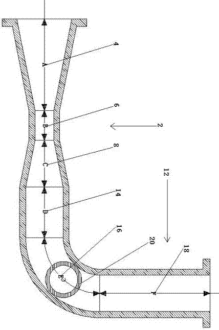
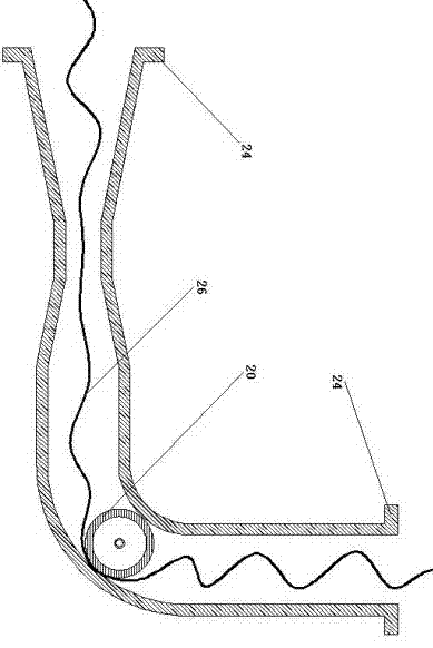

Image

  • Air overfeeding tube
  • Air overfeeding tube
  • Air overfeeding tube

Examples


Embodiment Construction

[0017] The present invention will now be further described in detail in conjunction with the accompanying drawings and embodiments. These drawings are all simplified schematic diagrams, only illustrating the basic structure of the present invention in a schematic manner, so it only shows the composition related to the present invention.

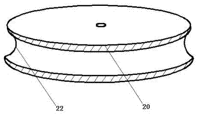
[0018] Such as figure 1 and figure 2 As shown, an air overfeeding pipe includes: preferably a Venturi tube 2 and a yarn outlet elbow 12 that is sealed and connected with the Venturi tube 2, and the two ends of the Venturi tube 2 are a compression section 4 and an expansion section 8 with horn-shaped openings , and the throat section 6 with a smaller cross-sectional radius is in the middle. In order to facilitate the free end of the Venturi tube 2 and the free end of the yarn outlet bend 12 to be sealed and communicated with external equipment, each free end is designed as a connecting ring 24 with an eversion, and a rubber ring is used as a...


PUM


Abstract

The invention relates to an air overfeeding tube which comprises a Venturi tube and a yarn discharging bending tube with a yarn guiding wheel. The Venturi tube is hermetically communicated with the yarn discharging bending tube, a compression section, a throat section and an expansion section are coaxially arranged in the Venturi tube, the yarn discharging bending tube is hermetically communicated with the throat section, and the yarn guiding wheel is located at the turning corner of the yarn discharging bending tube. The role of airflow can be accelerated by the aid of the Venturi tube, the yarn discharging bending tube is innovatively hermetically connected to the rear of the Venturi tube, the motion direction of yarns can be changed, the high-speed airflow integrally performs a certain tractive force upon each point of the yarns, the dispersed tractive force is large as a whole while the tractive force on each point of the yarns is limited, the airflow drives the yarns to move flexibly and cannot cause damages to the yarns and cannot increase yarn hairness on the surfaces of the yarns, and acceleration of the Venturi tube enables the overfeeding effect to be implemented easily.

Description

technical field [0001] The invention relates to a yarn air flow overfeeding device, in particular to an air overfeeding pipe. Background technique [0002] In the prior art, the overfeeding device of the yarn mostly adopts the form that the guide wheel drives the yarn to move. This technical solution can accelerate the yarn to realize overfeeding stably, but at the same time, the rotation of the guide wheel is too rigid and easy. Defects that cause damage to the yarn, the existing overfeeding device on the two-for-one twisting or twisting device mostly uses a wheel with bumps on the surface to drive the yarn movement, although the bumps are coated with yarn coating can reduce overfeeding The movement of the wheel to the yarn damages, but the damage cannot be avoided, and this technical solution will increase the hairiness on the yarn surface and reduce the yarn strength. Contents of the invention [0003] The invention overcomes the shortcomings of the prior art and p...

Claims


Application Information

Patent Timeline
IPC IPC(8): D01H13/04
Inventor 吴明华
Owner WUJIANG MINGJIA WEAVING
Learn More