A valve and a wheel

A wheel and valve technology, applied in the direction of wheels, valve details, diaphragm valves, etc., can solve the problems of increasing the running resistance and noise of the wheel, increasing the air resistance of the spoke, and increasing the surface area of ​​the spoke, so as to reduce the wind resistance and increase the rim dispersion. , the effect of improving performance

Inactive Publication Date: 2016-08-17
JIANGSU UNIV
View PDF9 Cites 2 Cited by
  • Summary
  • Abstract
  • Description
  • Claims
  • Application Information

AI Technical Summary

Problems solved by technology

At present, some companies have produced the spoke structure of hollow aluminum. The design of this hollow aluminum spoke structure can play a role in timely heat dissipation during the operation of the car, but the hollow aluminum structure will increase the surface area of ​​the spoke and increase the size of the wheel. Resistance and noise during operation, which limits the performance of the car in motion
In the prior art, there is also a technical solution for adding ventilation holes to ordinary spokes. The Chinese utility model patent with the patent announcement number of CN 202656778 U discloses a kind of open-type arc-shaped air holes evenly arranged around the periphery of the spoke disk, and the center of the disk surface The technical scheme of setting the middle hole and setting bolt holes around the middle hole can reduce the weight of the entire wheel to a certain extent. The heat dissipation function of the air holes is not required, but the design of the air holes will increase the air resistance of the spokes and increase the noise of the wheels; another disadvantage of this technical solution is that the middle holes are set on the spoke disk surface, and the spoke disk surface will be damaged during the actual driving of the car. It is not moving forward in the windward direction, so the effect of this technical solution is not obvious in the actual high-speed driving process of the car

Method used


Image

  • A valve and a wheel
  • A valve and a wheel
  • A valve and a wheel

Examples


Embodiment 1

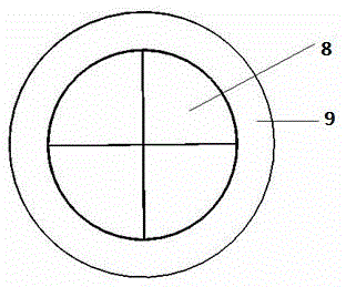
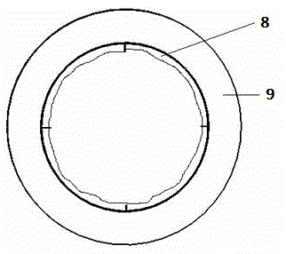
[0027] Embodiment 1: as figure 1 , figure 2 As shown, the valve provided by the present invention is composed of a shape memory metal sheet 8 and a frame 9, the shape memory metal sheet 8 is fixedly connected to the inner ring of the frame 9, and the number of shape memory metal sheets is multiple, for example figure 1 with Figure 7 As shown, the number of shape memory metal sheets 8 is four. The fixed connection method adopts welding, metal glue or clamping method. Such as figure 1 , when the ambient temperature is at or below a specific temperature, the shape memory metal sheet 8 remains closed, such as figure 2 , when the temperature exceeds a specific temperature, the shape memory metal sheet 8 is heated and shrinks to the surroundings, and the valve is opened, so as to achieve the function of controlling the fluid flow. It should be pointed out that the concept of low temperature, critical temperature and high temperature mentioned in the present invention is not ...

Embodiment 2

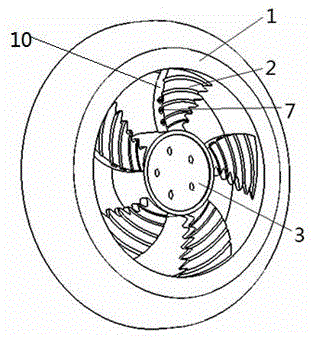
[0028] Embodiment 2: as image 3 , Figure 4 with Figure 5 As shown, in a wheel, the air inlet 5 of the ventilation hole 4 is arranged on the side of the spoke in the windward direction, and the air outlet 6 is arranged behind the spoke, and the air inlet 5 and the air outlet 6 communicate with each other to form the ventilation hole 4 . A ventilation hole 4 is provided on the side of the spoke 2, and a valve 7 provided by the present invention is provided at the air inlet 5 of the ventilation hole 4. The valve 7 is set at the air inlet 5 of the ventilation hole 4 through two technical schemes: the first scheme is that the valve 7 is directly fixedly connected with the air inlet 5; Figure 7 The second solution shown is that the valve 7 is fixedly connected to one end of a sleeve 11 and then the sleeve 11 and the valve 7 are inserted into the ventilation hole 4 as a whole. As a preferred technical solution, such as image 3 , Figure 4 with Figure 5 As shown, the venti...

Embodiment 3

[0029] Embodiment 3: as Image 6 As shown, the spoke 2 is connected to the hub 3, and the spoke 2 of the wheel forms an angle β with respect to the bottom surface of the hub 3, and the technical features of the angle range greater than 0° and less than 90° can reduce the windward area of ​​the spoke 2 as a whole, and correspondingly The windward area of ​​the air inlet 5 on the side surface 10 of the spoke 2 is increased to increase the heat dissipation performance. The spoke 2 is designed as a wing-shaped structure, and the preferred solution is to have a streamline groove structure on the surface of the spoke. During the operation of the car, the air flows through the rim groove of the spoke 2 through the asymmetric wing-shaped spoke 2. The technical features of asymmetry, wing shape or rim groove can reduce the air resistance and noise of the car running, and improve the driving performance of the car. . In this embodiment, the fixed connection method adopts welding, meta...


PUM


Abstract

The invention provides a valve and a wheel. The valve is characterized by comprising a plurality of shape-memory metal sheets and a frame, and the shape-memory metal sheets are fixedly connected to the inner circle of the frame. The wheel is lightened and has a timely radiating function in the process of an automobile driving in high speed. According to the technical scheme, the wheel is characterized in that vent holes are formed in spokes of the wheel, the air inlets of the vent holes are provided with the valves. In the process of the automobile driving in high speed, high temperature can be generated on the tire, the temperature of the rim is also high due to heat transmission, and the maximum temperature can be more than 100 DEG C. The spokes are provided with the vent holes provided with the valves, when the air speed or temperature is high, the shape-memory metal sheets open automatically, the valves are in opened states, and rim radiation is accelerated.

Description

technical field [0001] The invention belongs to the field of mechanical manufacturing, in particular to an automobile wheel with ventilation holes on the spokes. Background technique [0002] With the continuous rise of energy prices, the automotive industry is facing more and more difficult challenges of low energy consumption. The reduction of fuel consumption is multi-faceted, on the one hand is the lightweight design of the car. Therefore, in order to reduce fuel consumption, more and more attention has been paid to the lightweight design of automobiles. On the other hand, due to the current needs of environmental protection and energy saving, the lightweight of automobiles has become the trend of the world's automobile development. [0003] The wheel is an important safety component carried by the vehicle. The hub and spokes of the wheel not only bear the pressure of the vehicle's own weight vertically acting on the hub and spokes, but also are affected by the dynamic...

Claims


Application Information

Patent Timeline
Patent Type & Authority Patents(China)
IPC IPC(8): F16K7/12B60B19/10
CPCB60B19/10F16K7/20F16K31/002
Inventor 朱茂桃张鹏飞陈云
Owner JIANGSU UNIV
Why Eureka
Try Eureka