Energy-saving resistance-free check valve

A check valve, non-resistance technology, applied in the field of machinery, can solve the problems of not suitable for conveying medium with particles and easy to deposit, large fluid resistance of check valve, high energy consumption, convenient online replacement, preventing backflow of conveying medium, Reduce the effect of damage

Active Publication Date: 2014-07-16
上海东方威尔阀门有限公司
View PDF6 Cites 6 Cited by
  • Summary
  • Abstract
  • Description
  • Claims
  • Application Information

AI Technical Summary

Problems solved by technology

[0003] The object of the present invention is to provide an energy-saving non-resistance check valve. The energy-saving non-resistance check valve should solve the problem of large fluid resistance, large water hammer, high energy consumption and unsuitable transportation in the prior art. Technical issues with media with particles prone to deposits

Method used


Image

  • Energy-saving resistance-free check valve
  • Energy-saving resistance-free check valve
  • Energy-saving resistance-free check valve

Examples


Embodiment 1

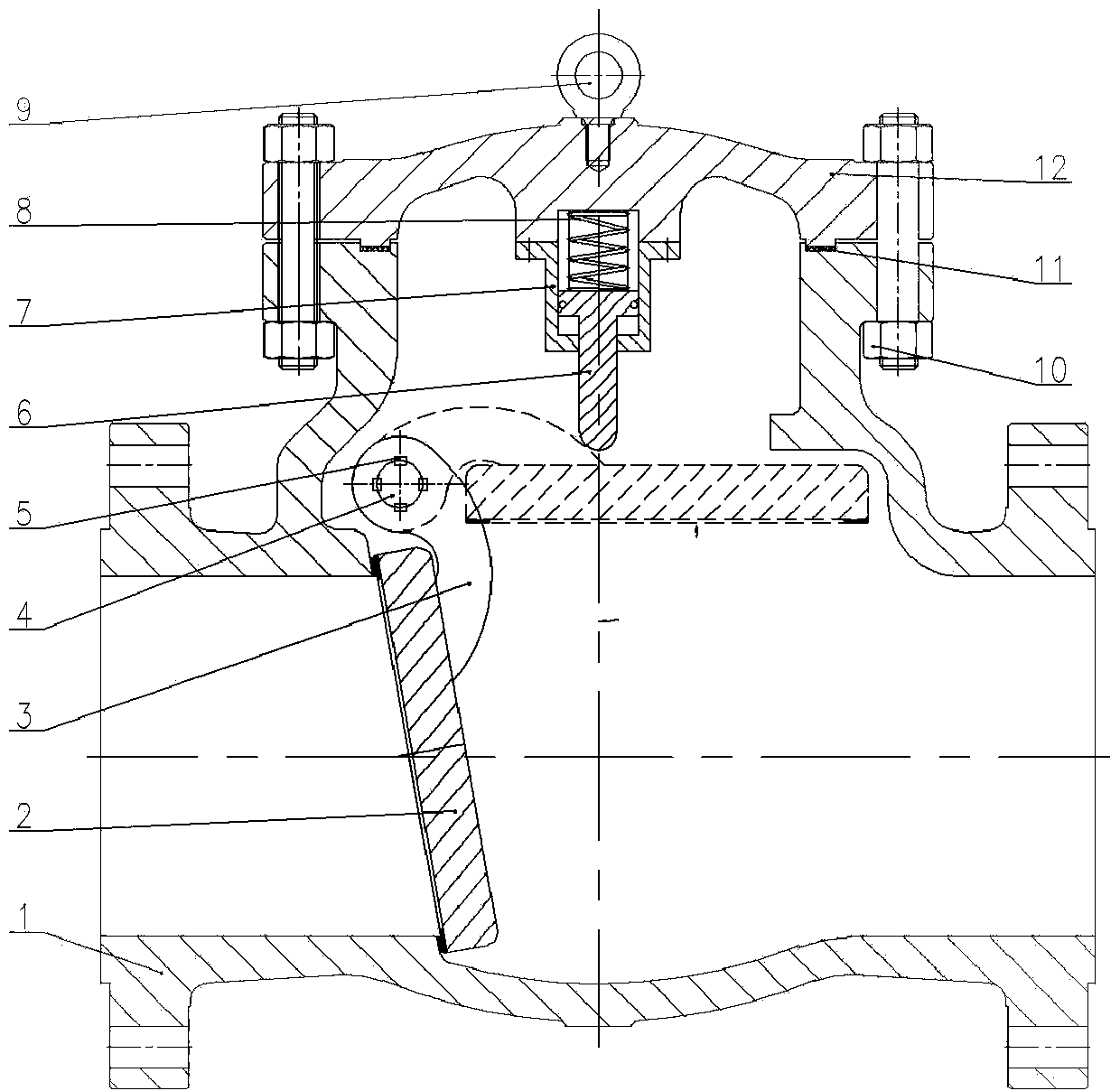
[0021] Such as figure 1 , figure 2 and image 3 As shown, the energy-saving non-resistance check valve of the present invention includes a valve body 1, a valve disc 2 and a valve cover 12, figure 1 The valve flap 2 in the dotted line position in represents its fully open position. The valve body 1 includes a medium inlet, a medium outlet and a valve chamber. The axial direction of the medium inlet coincides with the axial direction of the medium outlet. The valve chamber is located between the medium inlet and the medium outlet. The diameter of the valve chamber is larger than that of the medium inlet. , the bonnet 12 is in sealing connection with the valve body 1, the axial direction of the bonnet 12 is perpendicular to the axial direction of the medium inlet, the valve disc 2 is arranged in the valve cavity, wherein, a valve seat is arranged in the valve body 1, and the valve seat is located in the medium Between the inlet and the valve cavity, the axial direction of th...

Embodiment 2

[0031]The rocker 3 is connected with the valve flap 2 by bolts.

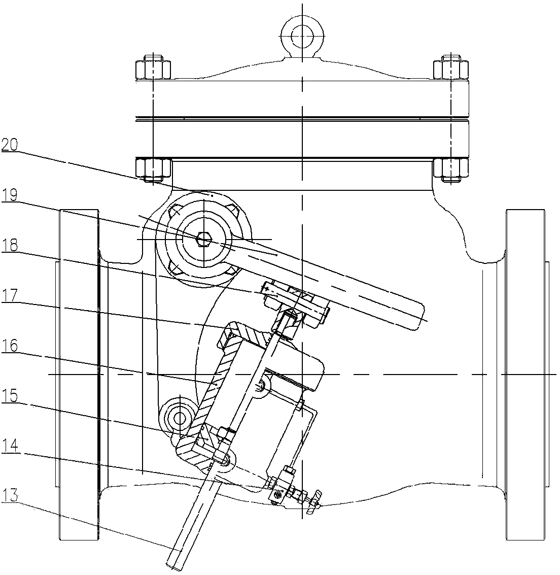
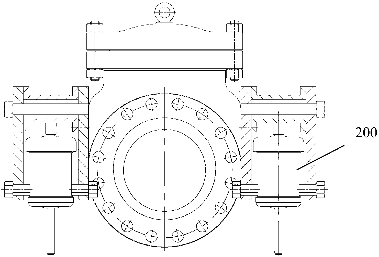
[0032] The working principle of the above embodiment is: the medium in the pipeline flows into the medium inlet of the valve body 1, the valve cavity is filled with medium, the medium pushes the valve disc 2 to swing, the valve disc 2 drives the valve stem 4 to rotate, and the valve stem 4 drives the rocker arm 19 rotates, the rocker arm 19 pulls the auxiliary valve rod 13 in the hydraulic slow closing device 200 to move upward, the auxiliary valve rod 13 drives the piston 15 to move, and the piston 15 pushes the hydraulic oil in the upper chamber of the hydraulic cylinder to flow into the lower chamber through the needle valve 14, so that The valve opens slowly. When the valve clack 2 is swung to a position parallel to the axial direction of the medium inlet, the valve clack 2 is located in the upturned chamber of the valve clack, and a flow channel with a full diameter is obtained between the medium inlet and ...


PUM

PropertyMeasurementUnit
Thicknessaaaaaaaaaa
Thicknessaaaaaaaaaa

Abstract

An energy-saving resistance-free check valve comprises a valve body, a valve clack and a valve deck. A valve rod is arranged in the valve body. The axial direction of the valve rod is perpendicular to the axial direction of a medium inlet. The valve rod penetrates through the upper portion of a valve cavity. The two ends of the valve rod extend out of the front side and the rear side of the valve body respectively. A rotating pair is arranged between the valve rod and the valve body. A rocker is connected to one side of the valve clack. The upper end of the rocker is connected with the valve rod. A limiting device is connected to the bottom side of the valve deck. The front side and the rear side of the valve body are respectively provided with a hydraulic slow-closing device. According to the energy-saving resistance-free check valve, gravity and buoyancy enable a medium to pass through the valve body fully without resistance when the valve clack is fully opened, so that the work efficiency of a water pump is improved, power consumption is lowered, and the energy-saving effect is achieved; since the valve body is in a streamline form, the medium cannot deposit in the valve cavity, and the energy-saving resistance-free check valve is suitable for conveying media with particles prone to deposition; in the closing process, water hammer can be effectively reduced, and damage of the water hammer to a pipeline and valve equipment is lowered; under the condition that the pressure of return water is very low, sealing can be guaranteed, and therefore the conveying medium can be effectively prevented from flowing back in the quick-closing process.

Description

Technical field: [0001] The invention relates to the mechanical field, in particular to a valve for fluid control, in particular to an energy-saving non-resistance check valve. Background technique: [0002] In the prior art, check valves are divided into two structural forms, swing type and lifting type, which have the following disadvantages respectively: (1) After the swing check valve is opened by a water pump, the valve clack is swung up and opened by fluid pressure , the full opening angle of the valve disc is 60°, which cannot reach the full-bore conveying medium, so that the flow rate is greatly reduced, and the valve disc is in a suspended state depending on the pressure of the conveying medium during the entire process of conveying the medium, resulting in very high fluid resistance. Large, the water pump frequently supplies water, and the power consumption is high. (2) The lifting check valve pushes the valve disc upwards through fluid pressure. Due to the short ...

Claims


Application Information

Patent Timeline
IPC IPC(8): F16K15/03F16K27/00F16K47/02F04B53/10
CPCF04B53/1037F16K15/03F16K27/0227F16K47/023
Inventor 美乐苏王长春尤长远吴进武
Owner 上海东方威尔阀门有限公司
Why Eureka
Try Eureka