Radiating fin with spherical protrusions
A technology of heat dissipation fins and heat exchange fins, which is applied in the field of defrosting of air source heat pumps and heat dissipation fins, can solve the problems of unsatisfactory defrosting effect, etc., and achieve the effect of improving defrosting efficiency, reducing influence and accelerating melting.
- Summary
- Abstract
- Description
- Claims
- Application Information
AI Technical Summary
Problems solved by technology
Method used
Image

Examples
Embodiment
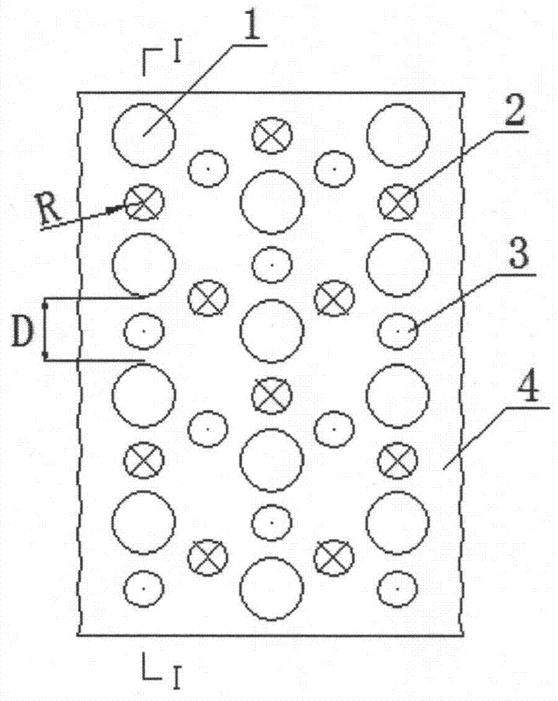
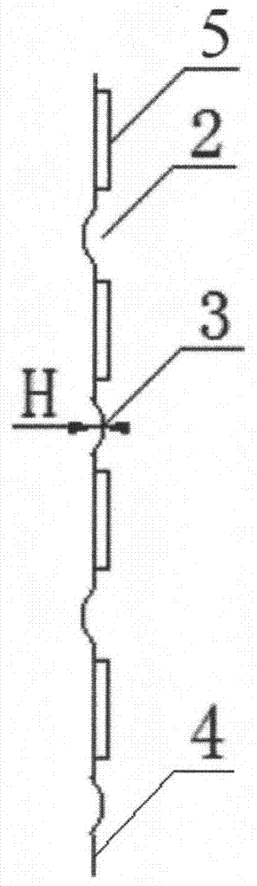
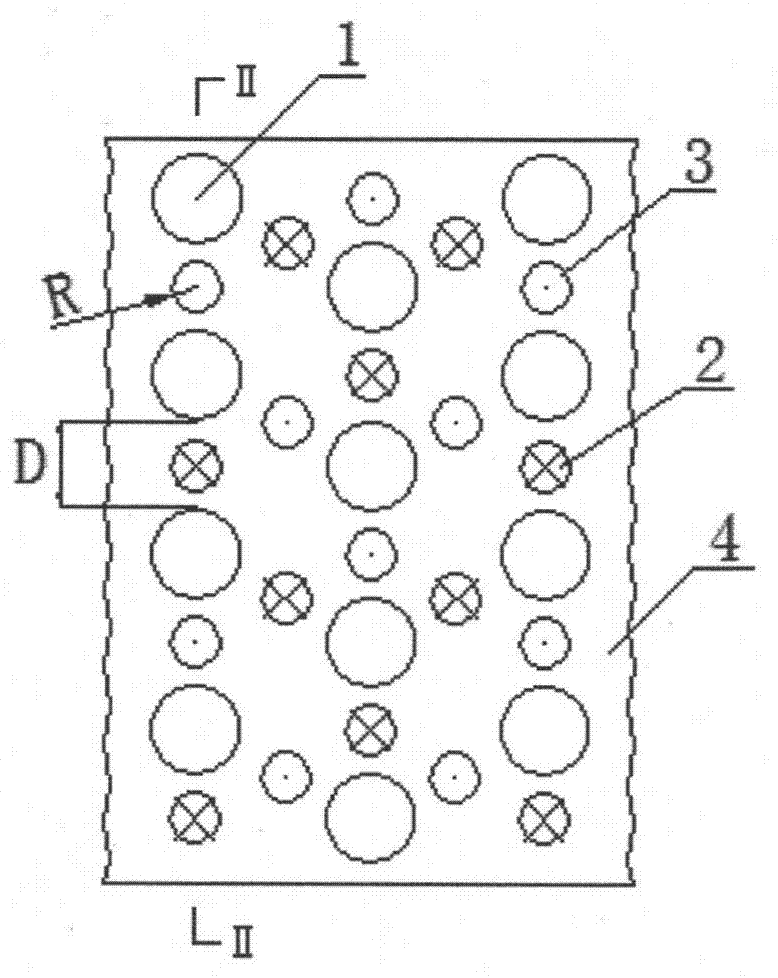
[0019] Such as Figure 1-2 As shown, it is a schematic diagram of the first heat dissipation fin with spherical protrusions, including a plate body 4, and the plate body 4 is provided with multiple rows of uniformly distributed tube holes 1 and spherical protrusions, and the adjacent two rows of tubes The holes 1 and the spherical protrusions are alternately arranged. The edge of each tube hole 1 is provided with an outward step 5 perpendicular to the fin. The arrangement of tube holes 1 and spherical protrusions on the first column is as follows: from top to bottom, tube holes 1, spherical protrusions 2 perpendicular to the fins inward, tube holes 1, outwards perpendicular to the fins Spherical protrusion 3, tube hole 1, spherical protrusion 2 perpendicular to the fin inward, tube hole 1, spherical protrusion 3 perpendicular to the fin outward, ... and so on; on the second column The arrangement of the tube hole 1 and the spherical protrusion is as follows: from top to bott...
PUM
 Abstract
Description
Claims
Application Information
 - R&D
- Intellectual Property
- Life Sciences
- Materials
- Tech Scout
- Unparalleled Data Quality
- Higher Quality Content
- 60% Fewer Hallucinations
Browse by: Latest US Patents, China's latest patents, Technical Efficacy Thesaurus, Application Domain, Technology Topic, Popular Technical Reports.
© 2025 PatSnap. All rights reserved.Legal|Privacy policy|Modern Slavery Act Transparency Statement|Sitemap|About US| Contact US: help@patsnap.com