Containment built-in spent fuel pool

A spent fuel pool and containment technology, applied to reactor fuel elements, cooling devices, nuclear power generation, etc., can solve problems such as loss of off-site power and inability to perform cooling functions, and achieve the effect of improving air cooling efficiency

Active Publication Date: 2014-07-16
SHANGHAI NUCLEAR ENG RES & DESIGN INST CO LTD
View PDF7 Cites 16 Cited by
  • Summary
  • Abstract
  • Description
  • Claims
  • Application Information

AI Technical Summary

Problems solved by technology

The cooling of the existing spent fuel pool is done in an active way, and th

Method used


Image

  • Containment built-in spent fuel pool
  • Containment built-in spent fuel pool
  • Containment built-in spent fuel pool

Examples


Example Embodiment

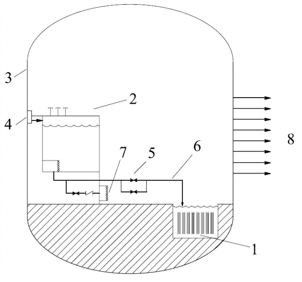
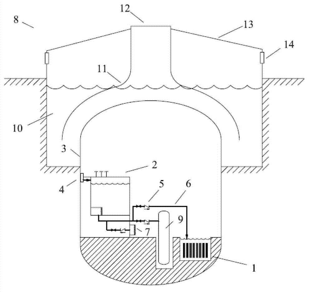
[0032] like figure 2Shown is the specific embodiment 1 of the spent fuel pool inside the containment according to the present invention. In this embodiment, the containment vessel 3 and the containment cooling water pool 10 are located in the reactor building 13, and the spent fuel pool 1 is arranged in the containment vessel 3. The height of the spent fuel pool 1 inside the containment vessel 3 is basically the same as that of the reactor cavity. The containment built-in water tank 2 is arranged in the containment vessel 3 at a higher level than the spent fuel pool 1. The top of the containment built-in water tank 2 is provided with The condensed water collector 4 is connected to the inner wall of the containment vessel 3, and the lower end of the water tank 2 inside the containment vessel is respectively connected to the spent fuel pool 1 and the reactor pressure vessel 9 through the pipeline 6, and the valve 5 is arranged on the pipeline 6 to ensure safety. The water tank ...

Example Embodiment

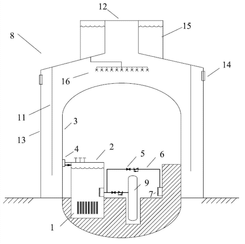
[0039] like image 3 As shown, it is the specific embodiment 2 of the spent fuel pool built in the containment of the present invention. The difference between this embodiment and the first embodiment is: (1) The spent fuel pool 1 is integrated in the lower part of the water tank 2 built in the containment, which eliminates the safety The water tank 2 inside the shell is the pipeline and valve for replenishing water to the spent fuel pool 1; the lower end of the water tank 2 inside the containment is connected to the reactor pressure vessel 9 through the pipeline 6, and the valve 5 is arranged on the pipeline 6; The shell cooling system 8, the containment cooling system 8 includes a deflector 11, an air outlet 12; a reactor building 13, an air inlet 14, a spray water tank 15, and a sprinkler 16, and the top of the reactor building 13 is provided with a spray water tank 15, The bottom of the spray water tank 15 is provided with a sprinkler 16, and the sprinkler 16 is located ab...


PUM


Abstract

The invention belongs to the technical field of nuclear power plant spent fuel pools and safe protection measure design thereof, and particularly relates to a containment built-in spent fuel pool, which comprises a spent fuel pool, a containment built-in water tank, a containment shell, a condensed water collector, valves, pipelines, a recirculation port and a containment cooling system, wherein the spent fuel pool and the containment built-in water tank are arranged inside the containment and are connected, the top of the containment built-in water tank is provided with the condensed water collector, the condensed water collector is connected with the inner wall of the containment shell, the lower end of the containment built-in water tank is connected with a reactor pressure vessel through the pipeline, the pipeline is provided with the valve, the recirculation port is connected on the outlet pipeline of the containment built-in water tank, and the containment cooling system is arranged on the outer portion of the containment shell. According to the present invention, the passive manner is adopted to cool the spent fuel without dependence on the external power supply so as to improve safety of the spent fuel pool under accidents and ensure radioactivity packaging and safe cooling of the spent fuel.

Description

technical field [0001] The invention belongs to the technical field of design of nuclear power plant spent fuel pools and safety protection measures thereof, and in particular relates to a spent fuel pool built in containment. Background technique [0002] The spent fuel pool is a facility for nuclear power plants to store spent fuel. In order to contain radioactivity, the water level of the spent fuel pool is several meters higher than the fuel. At the same time, the spent fuel emits decay heat, so it is necessary to continuously cool the spent fuel pool to ensure that the water level of the spent fuel pool will not drop due to the evaporation of water, resulting in the exposure of the spent fuel and ensuring the safety of the spent fuel. The cooling of the existing spent fuel pool is through active means, and the cooling function cannot be performed in the case of loss of off-site power. The lack of cooling of the spent fuel pool after the Fukushima accident caused the sp...

Claims


Application Information

Patent Timeline
IPC IPC(8): G21C19/07G21C15/18
CPCY02E30/30
Inventor 司胜义廖亮林千申屠军
Owner SHANGHAI NUCLEAR ENG RES & DESIGN INST CO LTD
Why Eureka
Try Eureka