Full-automatic spot welding machine for power battery pack electrode slice

A technology for power battery packs and electrode sheets, which is applied in resistance welding equipment, circuits, welding equipment, etc., can solve the problems of high investment in special spot welding power sources, increased equipment costs, and low welding efficiency, and is conducive to the transformation and upgrading of production lines. , Easy installation and replacement, and the effect of improving production efficiency

Active Publication Date: 2014-07-23
FUJIAN NEBULA ELECTRONICS CO LTD
View PDF10 Cites 30 Cited by
  • Summary
  • Abstract
  • Description
  • Claims
  • Application Information

AI Technical Summary

Problems solved by technology

[0003] (1) High welding labor intensity and low welding efficiency
[0004] (2) The qualified rate of welding is low, and it is easy to have defects such as virtual welding, battery core deformation, welding needle bonding, uneven solder joints, etc.
[0005] (3) The special spot welding power supply has a lot of investment and low utilization rate, which increases the cost of equipment
[0006] (4) The existing special equipment is relatively independent and cannot be connected with the customer's production line, which is not conducive to the transformation of the production line and affects the improvement of production efficiency

Method used


Image

  • Full-automatic spot welding machine for power battery pack electrode slice
  • Full-automatic spot welding machine for power battery pack electrode slice
  • Full-automatic spot welding machine for power battery pack electrode slice

Examples


Embodiment Construction

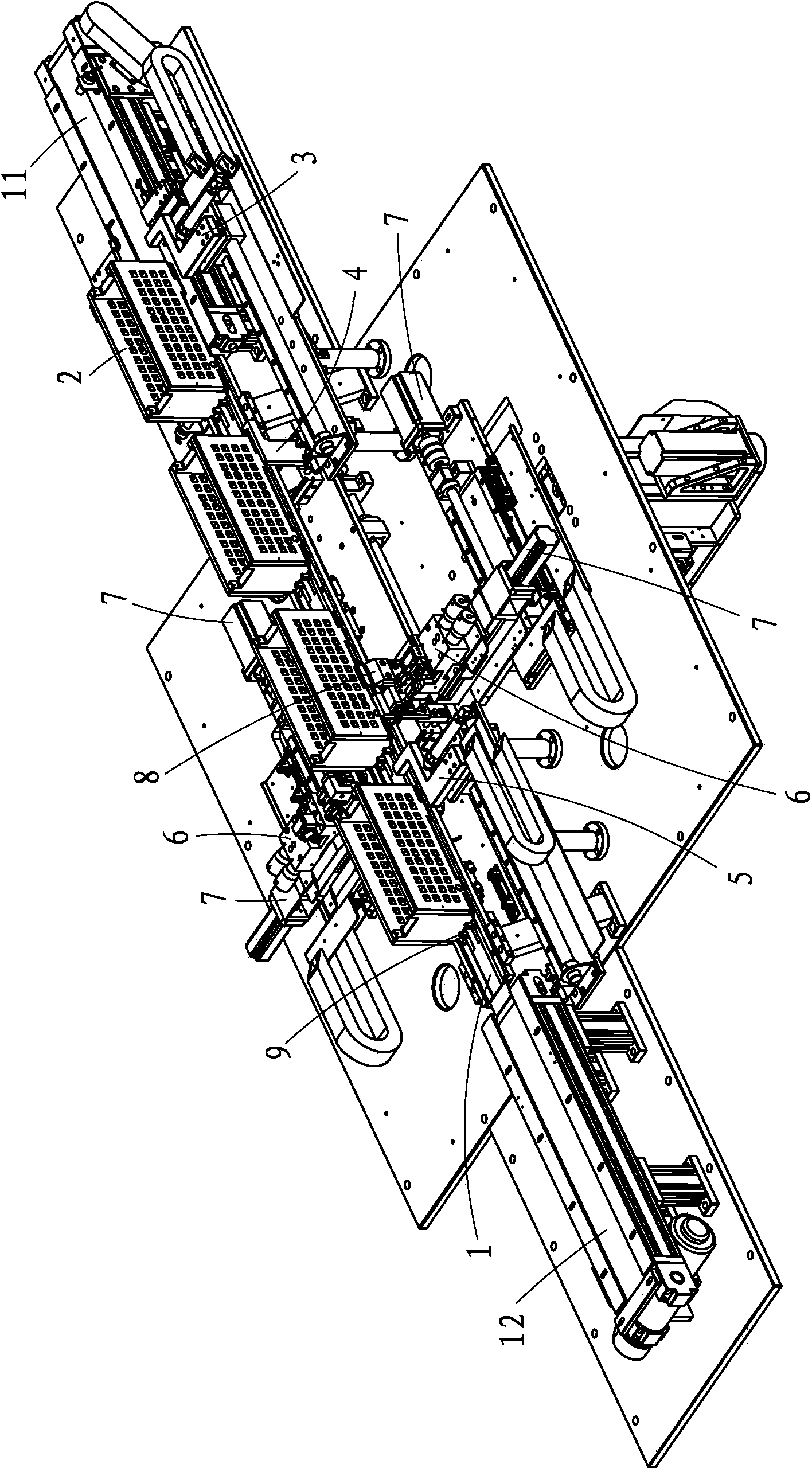
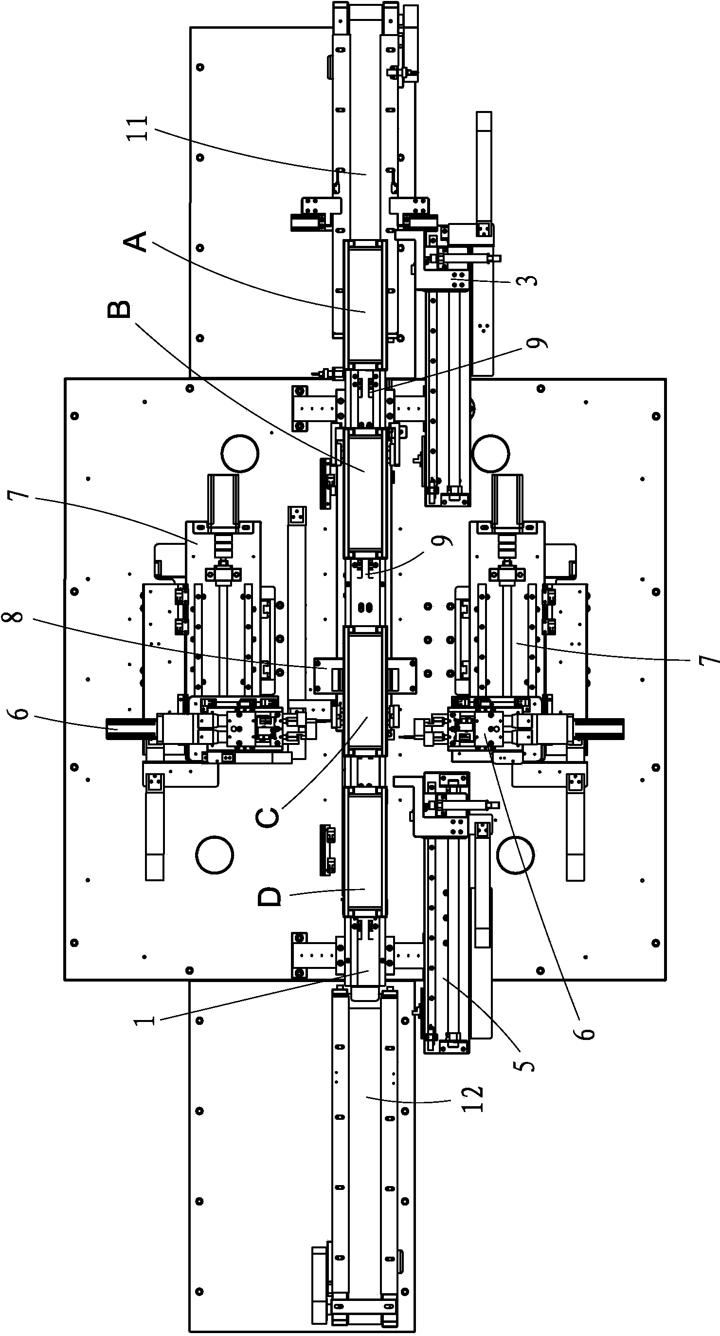
[0032] Such as Figure 1 to Figure 9 As shown, the fully automatic spot welding machine of the present invention comprises a track 1, a plurality of jigs 2, a jig advancing mechanism 3, a jig transfer guiding mechanism 4, a jig pushing out mechanism 5, two spot welding head 6, two three-axis motion mechanisms 7, and a positioning and clamping mechanism 8; the electrode sheet of the power battery pack to be spot-welded (not shown) is placed on the jig 2, and the jig 2 is Advance intermittently on track 1; Described two spot welding heads 6 are positioned at the both sides of track 1 respectively and are respectively arranged on a described three-axis motion mechanism 7, and control spot welding head 6 along three axes by this three axis motion mechanism 7 shaft movement; the jig propulsion mechanism 3 and the jig push-out mechanism 5 are respectively arranged on the feed end 11 and the discharge end 12 of the track 1, and the jig transfer guide mechanism 4 is arranged on the fe...


PUM


Abstract

The invention provides a full-automatic spot welding machine for a power battery pack electrode slice. The full-automatic spot welding machine comprises a rail, a plurality of jigs, a jig pushing-in mechanism, a jig transfer guide mechanism, a jig pushing-out mechanism, two spot welding heads, two three-axis motion mechanisms and a positioning clamping mechanism. The power battery pack electrode slice on which spot welding is about to be conducted is placed on the jigs to intermittently move forwards. The two spot welding heads are located on the two sides of the rail respectively and controlled by the three-axis motion mechanisms to move along three axes. The jigs are pushed in by the jig pushing-in mechanism for feeding, the fed jigs are pushed to spot welding positions one by one through the jig transfer guide mechanism and then are clamped through the positioning clamping mechanism, and then the jigs are pushed out through the jig pushing-out mechanism after spot welding is conducted through the spot welding heads. The intelligent user-related assembly line type full-automatic spot welding machine for the power battery pack electrode slice is high in efficiency, low in consumption, high in welding quality, and easy to link.

Description

technical field [0001] The invention relates to an automatic spot welding equipment for electrode sheets of power battery packs, especially suitable for the field of spot welding of electrode sheets of medium and large battery packs such as electric tools and electric vehicles. Background technique [0002] Large and medium-sized battery packs are mainly used in power tools, notebook computers, electric vehicles and other fields. At present, most manufacturers in China use semi-automatic spot welding, and its shortcomings are mainly manifested in: [0003] (1) The welding labor intensity is high and the welding efficiency is low. [0004] (2) The qualified rate of welding is low, and it is easy to have defects such as virtual welding, deformation of the battery core, bonding of welding needles, and uneven solder joints. [0005] (3) The dedicated spot welding power supply requires a lot of investment, and the utilization rate is low, which increases the cost of equipment. ...

Claims


Application Information

Patent Timeline
Patent Type & Authority Applications(China)
IPC IPC(8): B23K37/02B23K37/04B23K37/00
CPCB23K11/115B23K11/314B23K11/36B23K37/0247B23K37/0252B23K37/0408B23K2101/38
Inventor 李有财赖秋凤许盛均郭金鸿黄思强
Owner FUJIAN NEBULA ELECTRONICS CO LTD
Why Eureka
Try Eureka