
Heat dissipation device and method for local high heat flow in limited space

A technology of limited space and heat dissipation device, applied in indirect heat exchangers, lighting and heating equipment, cooling/ventilation/heating renovation, etc. Unable to meet the local high heat flux density heat dissipation requirements and other problems, to achieve the effect of improving the overall heat exchange capacity, increasing the surface area, and reducing the space

Active Publication Date: 2015-11-04
ZHEJIANG UNIV
View PDF5 Cites 0 Cited by
  • Summary
  • Abstract
  • Description
  • Claims
  • Application Information

AI Technical Summary

Problems solved by technology

[0005] (1) External reinforced heat exchange parts such as fins increase the space for heat dissipation, which restricts the development of miniaturization and compactness of system devices
[0006] (2) The heat flux density of fins and other heat transfer through air convection still cannot meet the heat dissipation requirements of local high heat flux density, and more effective heat dissipation methods are needed

Method used


Image

  • Heat dissipation device and method for local high heat flow in limited space
  • Heat dissipation device and method for local high heat flow in limited space
  • Heat dissipation device and method for local high heat flow in limited space

Examples


Embodiment Construction

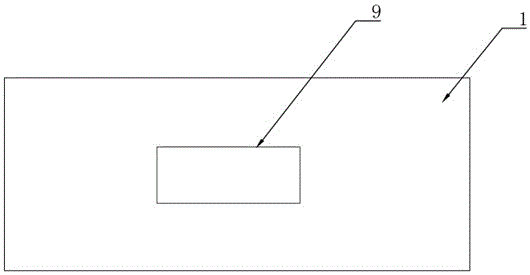
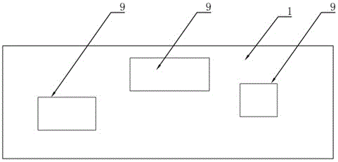
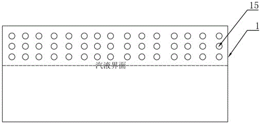
[0020] Such as Figure 1-5 As shown, the heat dissipation device with local high heat flow in a limited space includes a lower cover plate 1, a water inlet pipe 2, an inlet pipe connector 3, a vacuum pumping port 4, an upper cover plate 5, a support column 6, an accommodation space 7, a super-hydrophilic Micro-nano structure coating 8, evaporation area 9, micro-channel tube bundle 10, outlet pipe connector 11, water outlet pipe 12, local heating source 13, substrate 14, micro-channel hole 15; the lower cover plate 1 and the upper cover plate 5 are welded Connect to form a closed accommodation space 7; a support column 6 is provided between the lower cover 1 and the upper cover 5, and one end of the support column 6 is welded to the upper cover 5; the upper cover 5 is provided with a vacuum port 4; The inner surface of the lower cover plate 1 is coated with a super-hydrophilic micro-nano structure coating 8; the bottom surface of the lower cover plate 1 is mechanically pressed ...


PUM


Abstract

The invention discloses a device and method for cooling partial high heat flow within a limited space. The device comprises a lower cover board, a water inlet pipeline, an inlet pipeline connector, a vacuum pumping port, an upper cover board, a supporting column, a containing space, a super-hydrophilic micro-nano structural coating, an evaporation area, a micro-channel tube bundle, an outlet pipeline connector, a water outlet pipeline, a partial heating source, a base board and a micro-channel hole. The micro-channel tube bundle is arranged in the condensation section space of an internal pipe of a guide panel heat pipe, so that the space of a whole cooler device is largely reduced. Due to the arrangement of micro-channel tubes, the cooling superficial area is enlarged, the coefficient of heat exchange is increased through forced convection of water in the micro-channel tubes, and the heat exchange capability of the condensation end is enhanced. The boiling heat exchange capability of the evaporation area is enhanced through the super-hydrophilic micro-nano structural coating, and finally the overall heat exchange capability of the device is enhanced.

Description

technical field [0001] The invention relates to a heat dissipation device and method for local high heat flow in a limited space, and belongs to the technical field of enhanced heat exchange of electronic devices. Background technique [0002] With the development of nanotechnology, the volume of electronic devices is smaller, but the heat flux per unit area is getting higher and higher. Efficient and rapid heat dissipation in a limited space has become one of the main constraints restricting the development of electronic device manufacturing. [0003] As a kind of heat conduction diode, heat pipe has extremely high heat transfer capacity, and heat pipe or vapor chamber provides an option for realizing efficient heat exchange in a limited space. At present, the use of heat pipes or vapor chambers as the heat dissipation of key components in equipment such as servers, computers, base stations, and LEDs, such as CPUs, has been widely used. [0004] But for the existing vapor ...

Claims


Application Information

Patent Timeline
Patent Type & Authority Patents(China)
IPC IPC(8): F28D15/02H05K7/20
Inventor 张良
Owner ZHEJIANG UNIV
Learn More