Railway vehicle real vehicle bump test system for coupling passenger behavior detection

A test system and rail vehicle technology, applied in the field of rail vehicle crash test system, can solve problems such as inability to directly use for reference, and achieve the effects of simple and easy operation, scientific and reasonable structure

Active Publication Date: 2014-07-23
CENT SOUTH UNIV
View PDF6 Cites 13 Cited by
  • Summary
  • Abstract
  • Description
  • Claims
  • Application Information

AI Technical Summary

Problems solved by technology

It cannot be directly used for reference, and the actual vehic

Method used


Image

  • Railway vehicle real vehicle bump test system for coupling passenger behavior detection
  • Railway vehicle real vehicle bump test system for coupling passenger behavior detection

Examples


Embodiment 1

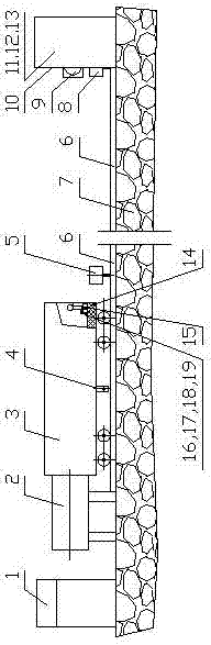
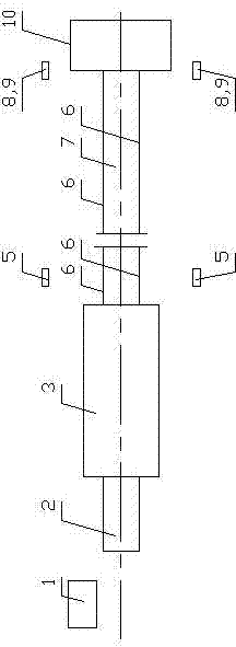
[0056] A steel rail 6 is set on the foundation 7 between the launcher 2 and the impact wall 10; the real vehicle 3 is placed on the steel rail 6, and the launcher 2 is installed on the end of the real vehicle 3 facing away from the impact wall 10; At least one experimental dummy 16 is arranged at both ends and in the middle, and the experimental dummy 16 is placed on the seat 15 in an unconstrained sitting position, and the seat 15 is fixed on the floor 14; the experimental dummy 16 is a standard dummy, and each A pressure sensor 17, a displacement sensor 18 and an acceleration sensor 19 are arranged on the head, neck, chest and back of the experimental dummy 16; the central console 1 is connected to the pressure sensor 17, the displacement sensor 18 and the acceleration sensor 19 by wired or wireless means . During the impact test: the central console 1 controls the work of the transmitter 2, the impact speed measuring device 8, the high-speed photography device 9, the force ...

Embodiment 2

[0058] It is basically the same as in Embodiment 1, except that each experimental dummy 16 is equipped with a rigid frame, and the beams of the frame correspond to the head, neck, back, front chest, abdomen, legs and hands of the experimental dummy 16. The pressure sensor 17, the displacement sensor 18 and the acceleration sensor 19 are arranged at the positions of the parts; the central console 1 is connected with the pressure sensor 17, the displacement sensor 18 and the acceleration sensor 19 by wired or wireless means.

Embodiment 3、4

[0060] They are basically the same as in Embodiment 1, except that the impact wall 10 includes a uniform force plate 11, a force measuring acquisition device and an impact pier 13, the uniform force plate 11 faces the real vehicle 3, and the force measurement acquisition device is located between the uniform force plate 11 and the impacting pier. between the piers 13; the force measurement acquisition device is a force sensor array 12; the central console 1 is electrically connected to the force sensor array 12 and receives impact data.


PUM


Abstract

A railway vehicle real vehicle bump test system for coupling passenger behavior detection comprises a central control table, an emitter, a real vehicle and a bump wall. The real vehicle is arranged on a steel rail between the emitter and the bump wall. A bump speed measuring device and a high speed photography device are installed on the side of the bump wall. Experiment dummies are arranged at two ends and in the middle of a passenger area in a carriage of the real vehicle, the experiment dummies are arranged on seats in a non-restricting sitting posture, and a pressure sensor, a displacement sensor and an acceleration sensor are arranged on a body of each experiment dummy. A brake device, a speed adjusting brake device connector and a debugging speed measuring device are used under the debugging condition. In the bump test process, the brake device deviates from the speed adjusting brake device, and a central control table program controls a relevant device to receive and store data. The power-free free sliding distance of the real vehicle is at least 1.1 times as long as the effective journey of the emitter, and the test bump speed of the real vehicle and the bump wall is not lower than 25kilos per hour. Meanwhile, the coupling passenger behavior detection is conducted.

Description

technical field [0001] The invention relates to a rail vehicle actual vehicle impact test system coupled with occupant behavior detection. Background technique [0002] Train collision accidents seriously threaten the safety of passengers. In order to reduce the losses caused by train collision accidents, the development of impact-resistant and energy-absorbing car bodies is an important way to reduce the losses caused by train collision accidents, and it is also an inevitable trend in the development of the world's railway passenger car body structures (including urban rail transit vehicles). In the study of the crashworthiness of rail vehicle structures, the real vehicle impact test is an irreplaceable research method that can truly reflect the impact process. The crashworthy and energy-absorbing vehicle body must be developed based on the actual vehicle crash test. [0003] Chinese patent application number is 200610046823.3, and the name is called " automobile passive ...

Claims


Application Information

Patent Timeline
IPC IPC(8): G01M17/08G01M7/08
Inventor 田红旗姚松姚曙光谢素超彭勇周伟张健
Owner CENT SOUTH UNIV
Why Eureka
Try Eureka