Eureka AIR delivers breakthrough ideas for toughest innovation challenges, trusted by R&D personnel around the world.

Radiographic apparatus and an image processing method therefor

一种摄影装置、放射线的技术,应用在测量装置、根据投影再现、使用辐射进行材料分析等方向,能够解决没有提出计算时间、变长等问题,达到确保收敛精度、计算高速化的效果

Active Publication Date: 2014-07-23
SHIMADZU SEISAKUSHO LTD
View PDF7 Cites 12 Cited by
  • Summary
  • Abstract
  • Description
  • Claims
  • Application Information

AI Technical Summary

Problems solved by technology

In addition, in the existing methods, no speed-up method has been proposed to solve the problem that the calculation time in the nonlinear optimization operation becomes longer as the number of parameters increases.

Method used


Image

  • Radiographic apparatus and an image processing method therefor
  • Radiographic apparatus and an image processing method therefor
  • Radiographic apparatus and an image processing method therefor

Examples


Embodiment Construction

[0045] Hereinafter, embodiments of the present invention will be described with reference to the drawings.

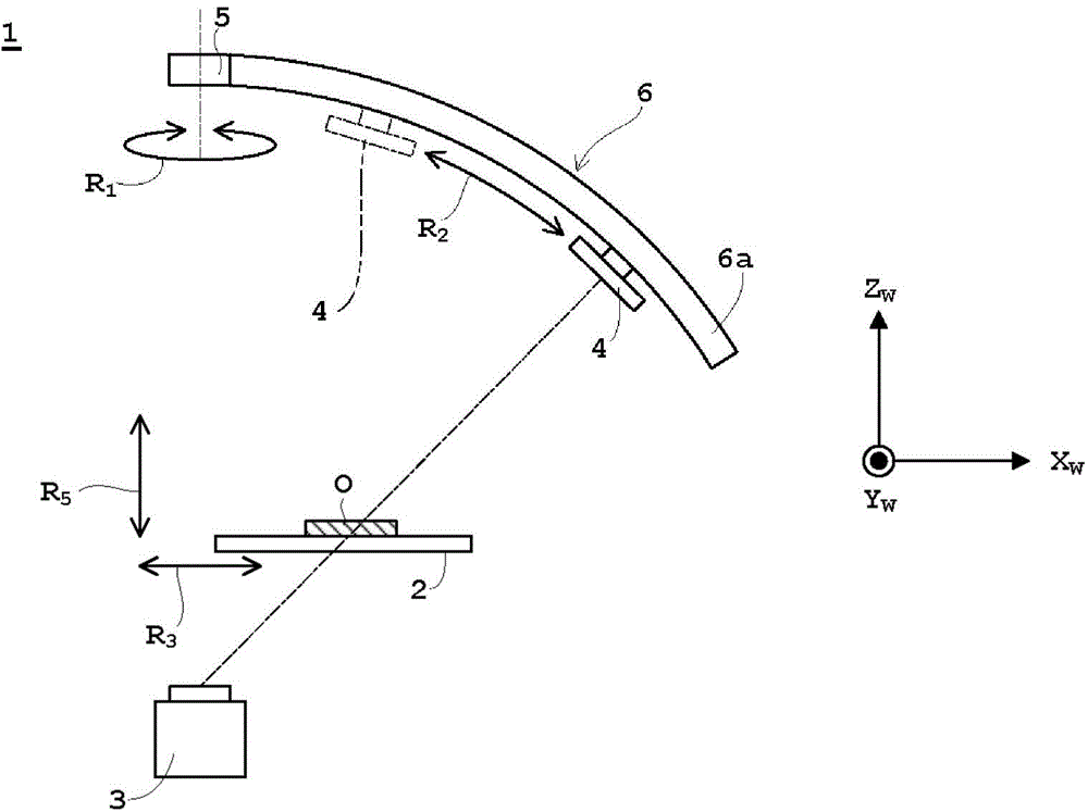
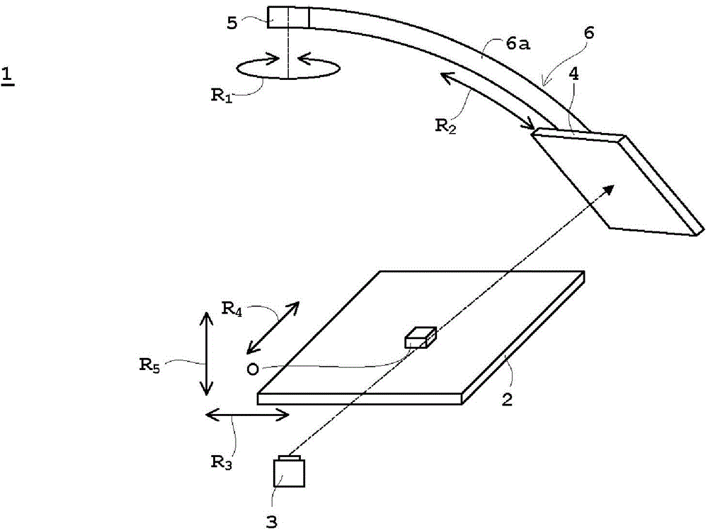
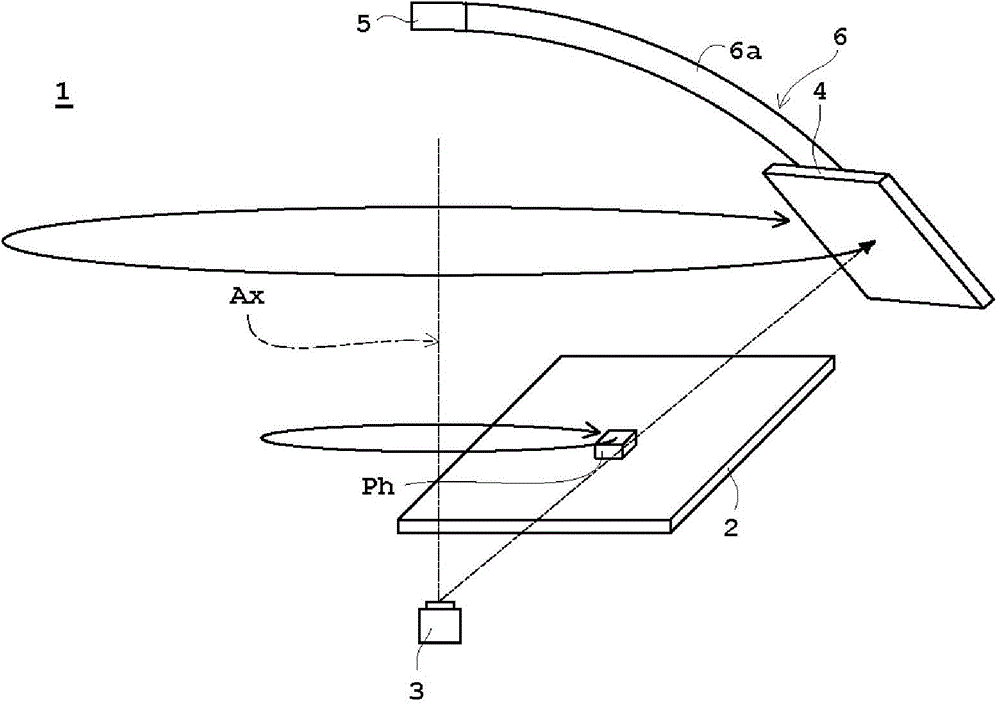
[0046] figure 1 is a schematic configuration diagram of the X-ray inspection apparatus according to the embodiment, figure 2 is a schematic perspective view of the X-ray inspection apparatus according to the embodiment, image 3 It is a schematic perspective view of an X-ray inspection apparatus according to an embodiment of a calibration method based on a calibration phantom, Figure 4 It is a schematic perspective view of the X-ray inspection apparatus according to the embodiment in which each coordinate system is described at the same time, Figure 5 It is a block diagram of the X-ray inspection apparatus concerning an Example. In this embodiment, an X-ray inspection apparatus will be used as an example for description as a radiographic apparatus.

[0047] Such as figure 1 As shown, the X-ray inspection apparatus 1 includes a table 2 on which an object O is p...


PUM


Abstract

Initial values A1P1M1 . . . AnPnMn of parameters representing a geometric relationship between an X-ray tube, a stage and a flat panel X-ray detector are estimated, a least squares solution (pw)i of characteristic point three-dimensional coordinates is estimated, and only limited parameters are updated until reprojection square errors converge. Thus, based on known radiographic conditions, initial values of the parameters are estimated, and a nonlinear optimization operation is carried out on only the parameters considered, in view of mechanisms and drive characteristics of the apparatus, to have large errors between the initial values of the parameters and the parameters at a time when radiography is actually carried out. As a result, the calculation can be speeded up, while securing the convergence accuracy of the nonlinear optimization operation, by using the radiographic conditions, i.e. information on tomography.

Description

technical field [0001] The present invention relates to a radiographic apparatus and an image processing method for radiographic imaging based on a projection image obtained by detecting radiation irradiated from a radiation irradiation unit and transmitted through an object by a radiation detection unit. Background technique [0002] As radiation, X-rays will be used as an example for description. In addition, as objects, there are mounting substrates, through-holes / patterns / soldering parts of multilayer substrates, electronic components before mounting such as integrated circuits (IC: Integrated Circuit) arranged on trays, metal castings, and video recording devices. Such molded products, etc. Specifically, it is used in the inspection of electronic components (for example, inspection of substrate wiring, inspection of BGA (Ball Grid Array), soldered part, void, etc.), inspection of internal defects of these objects, etc. . [0003] In conventionally known CT (computed ...

Claims


Application Information

Patent Timeline
Patent Type & Authority Applications(China)
IPC IPC(8): G01N23/04
CPCG01N23/046G01N2223/3304G01N2223/419G01N2223/6113G06T11/005
Inventor 田川雄介
Owner SHIMADZU SEISAKUSHO LTD
Why Eureka
Eureka Blog
Learn More