Optical fiber on-line surface plasmon Airy light beam generator

A surface plasmon and beam generator technology, applied in the optical field, can solve the problems of low precision, large size, low laser damage threshold, etc., and achieve the effects of small size, flexible production and high integration.

Inactive Publication Date: 2014-07-23
HARBIN ENG UNIV
View PDF3 Cites 11 Cited by
  • Summary
  • Abstract
  • Description
  • Claims
  • Application Information

AI Technical Summary

Problems solved by technology

In most experimental systems, the Airy beam is realized by passing a Gaussian beam through a phase-type spatial light modulator (Spatial Light Modulator, SLM), but the spatial light modulator has some disadvantages, such as large size, low precision, due to the material Due to its low laser damage threshold, etc.

Method used


Image

  • Optical fiber on-line surface plasmon Airy light beam generator
  • Optical fiber on-line surface plasmon Airy light beam generator
  • Optical fiber on-line surface plasmon Airy light beam generator

Examples


Embodiment 1

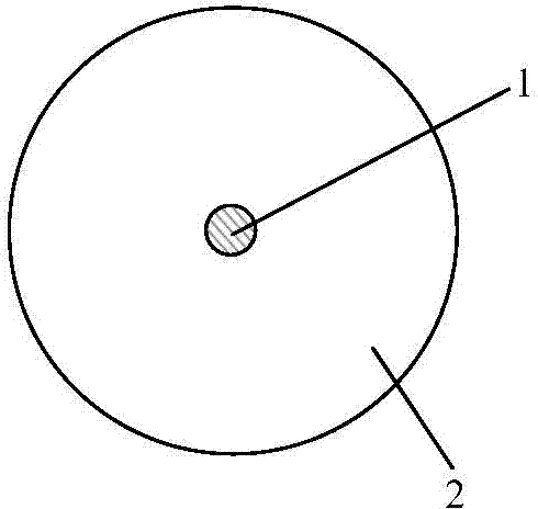
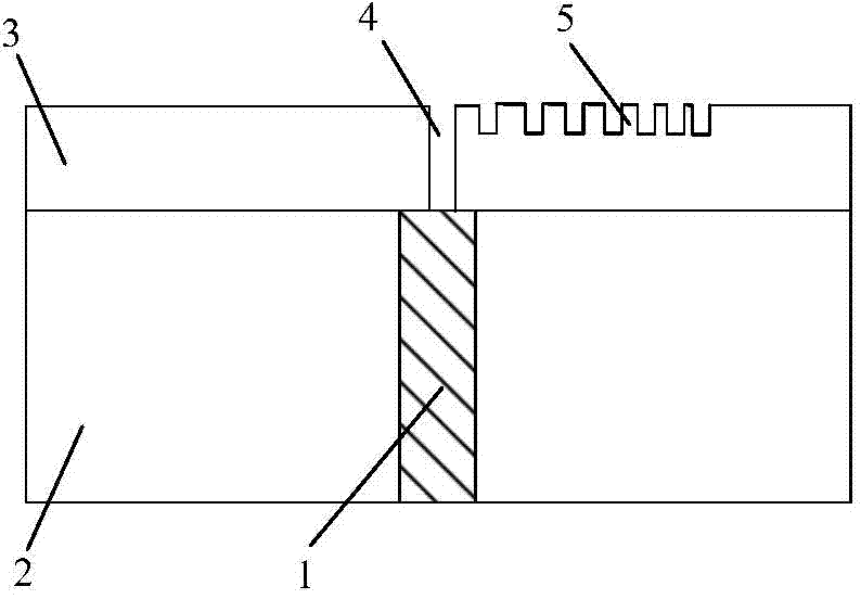
[0030] Fiber-optic online surface plasmon dual Airy beam generator (Fig. 1 and Figure 5 ), the end face of the optical fiber is coated with a 200nm thick gold film 3, and then a single slit 4 with a depth of 200nm, a width of 130nm and a length of 3 microns is carved on the central axis of the fiber core 1 by using focused ion beam technology. Then engrave an array of microgrooves 5 on the right side of the fiber core, the interval between adjacent grooves is a gradient change, and the spatial position of each groove from a single slit is determined by the formula φ 0 + k spp x + 2 nπ = 2 3 ( x x 0 ) 3 / 2 + ...

Embodiment 2

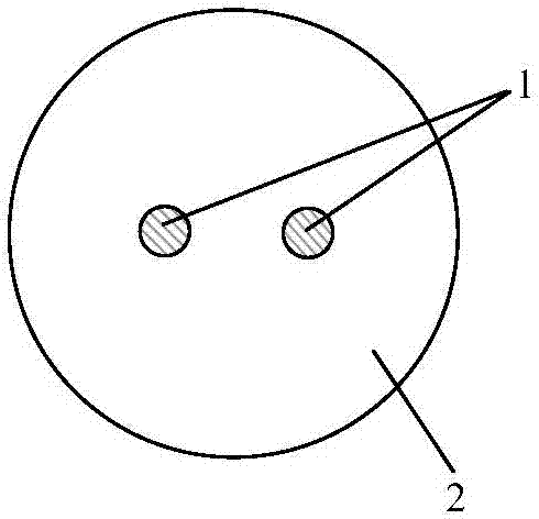
[0032] Online surface plasmon dual Airy beam generator based on dual-core fiber (Fig. 2 and Figure 6 ), the two core materials of the dual-core fiber are exactly the same size, symmetrically distributed, and the spacing is 50 microns. First, make a mark on the side of the fiber to facilitate micromachining to find the position of the fiber core. A gold film 3 with a thickness of 200 nanometers is plated on the end face of the dual-core optical fiber, and then a single slit 4-1 and 4 with a depth of 200 nanometers, a width of 130 nanometers, and a length of 3 microns is respectively carved on the central axis of the two fiber cores 1 by using focused ion beam technology. -2. Then engrave array microgrooves 5-1 and 5-2 of the same structure on the right side of the fiber core 1-1 and the left side of the fiber core 1-2, the interval between adjacent grooves is a gradient change, and each groove distance is one The spatial position of the seam is given by the formula ...

Embodiment 3

[0034] On-line surface plasmon dual Airy beam generator based on dual-core fiber ( image 3 ), the two core materials of the dual-core fiber are exactly the same size, symmetrically distributed, and the spacing is 50 microns. First, make a mark on the side of the fiber to facilitate micromachining to find the position of the fiber core. A gold film 3 with a thickness of 200 nanometers is plated on the end face of the dual-core optical fiber, and then a single slit 4-1 and 4 with a depth of 200 nanometers, a width of 130 nanometers, and a length of 3 microns is respectively carved on the central axis of the two fiber cores 1 by using focused ion beam technology. -2. Then engrave array microgrooves 5-1 and 5-2 of the same structure on the right side of the fiber core 1-1 and the left side of the fiber core 1-2, the interval between adjacent grooves is a gradient change, and each groove distance is one The spatial position of the seam is given by the formula ...


PUM


Abstract

The invention belongs to the technical field of optics, and particularly relates to an optical fiber on-line surface plasmon Airy light beam generator used for optical micro capturing. The optical fiber on-line surface plasmon Airy light beam generator is formed in the mode that a metal film is plated on the end surface of an optical fiber and then a single slit and an array microgroove structure are formed in the surface of the metal film in an inscribing mode, the thickness of the metal film is 100-300 nanometers, the single slit is formed in the central axis of a fiber core, the depth of the single slit is the same as the thickness of the metal film, and the width of the single slit is 50-200 nanometers. The depth of the array microgroove structure is 20-90 nanometers, and the width of the array microgroove structure is 100-400 nanometers. The Airy light beam generator is small in size and high in integration level, can achieve all-fiber integration easily, can be interconnected with the existing optical fiber technology and is of great significance in particle control of micro-optics.

Description

technical field [0001] The invention belongs to the field of optical technology, in particular to an optical fiber online surface plasmon Airy beam generator used in optical micro-capturing. Background technique [0002] Beam shaping can provide a variety of unusual beam profiles, which plays an important role in the field of optical micro-trapping and has become a research hotspot. Bessel beams, Laguerre-Gaussian beams, and collimated beams have been used in optical tweezers systems and lasers. Due to the unusual characteristics of Airy beams such as lateral acceleration, non-diffraction, and self-reconfiguration, this feature can exist at a long distance, so the use of light scattering force in the manipulation of tiny particles can provide guidance at a large distance, which has attracted research. attention of personnel. In most experimental systems, the Airy beam is realized by passing a Gaussian beam through a phase-type spatial light modulator (Spatial Light Modulat...

Claims


Application Information

Patent Timeline
Patent Type & Authority Applications(China)
IPC IPC(8): G02B27/09G02B27/42
Inventor 关春颖史金辉杨菁苑立波
Owner HARBIN ENG UNIV
Why Eureka
Try Eureka