Charging system and method for mobile terminal and charger

A mobile terminal and charging method technology, which is applied in the charging system of mobile terminals and the field of chargers, can solve the problems of reducing the service life of lithium batteries, increasing the number of repeated charging and discharging of lithium batteries, and attenuating the capacity of lithium batteries, so as to prolong the actual use life, avoiding overcharge or overdischarge state, and reducing loss

Active Publication Date: 2014-07-23
KENIU NETWORK TECH BEIJING
View PDF4 Cites 15 Cited by
  • Summary
  • Abstract
  • Description
  • Claims
  • Application Information

AI Technical Summary

Problems solved by technology

In the process of realizing the present invention, the inventor found that the prior art has at least the following problems: if the user forgets to unplug the charger, the lithium battery will be in an overcharged state for a long time after it is fully charged, thereby reducing the service life of the lithium battery
[0004] In addition, although some lithium batteries can stop the charger from continuing to charge the lithium battery when it is fully charged through its own protection circuit, when the lithium battery is depleted, the charger will start charging the lithium battery again. Therefore, It will increase the number of times the lithium battery is repeatedly charged and discharged meaninglessly, resulting in the attenuation of the lithium battery capacity and reducing the service life of the lithium battery

Method used


Image

  • Charging system and method for mobile terminal and charger
  • Charging system and method for mobile terminal and charger
  • Charging system and method for mobile terminal and charger

Examples


Embodiment Construction

[0021] Embodiments of the present invention are described in detail below, examples of which are shown in the drawings, wherein the same or similar reference numerals designate the same or similar elements or elements having the same or similar functions throughout. The embodiments described below by referring to the figures are exemplary and are intended to explain the present invention and should not be construed as limiting the present invention.

[0022] In addition, the terms "first" and "second" are used for descriptive purposes only, and cannot be interpreted as indicating or implying relative importance or implicitly specifying the quantity of indicated technical features. Thus, a feature defined as "first" and "second" may explicitly or implicitly include one or more of these features. In the description of the present invention, "plurality" means two or more, unless otherwise specifically defined.

[0023] Any process or method descriptions in flowcharts or otherwis...


PUM


Abstract

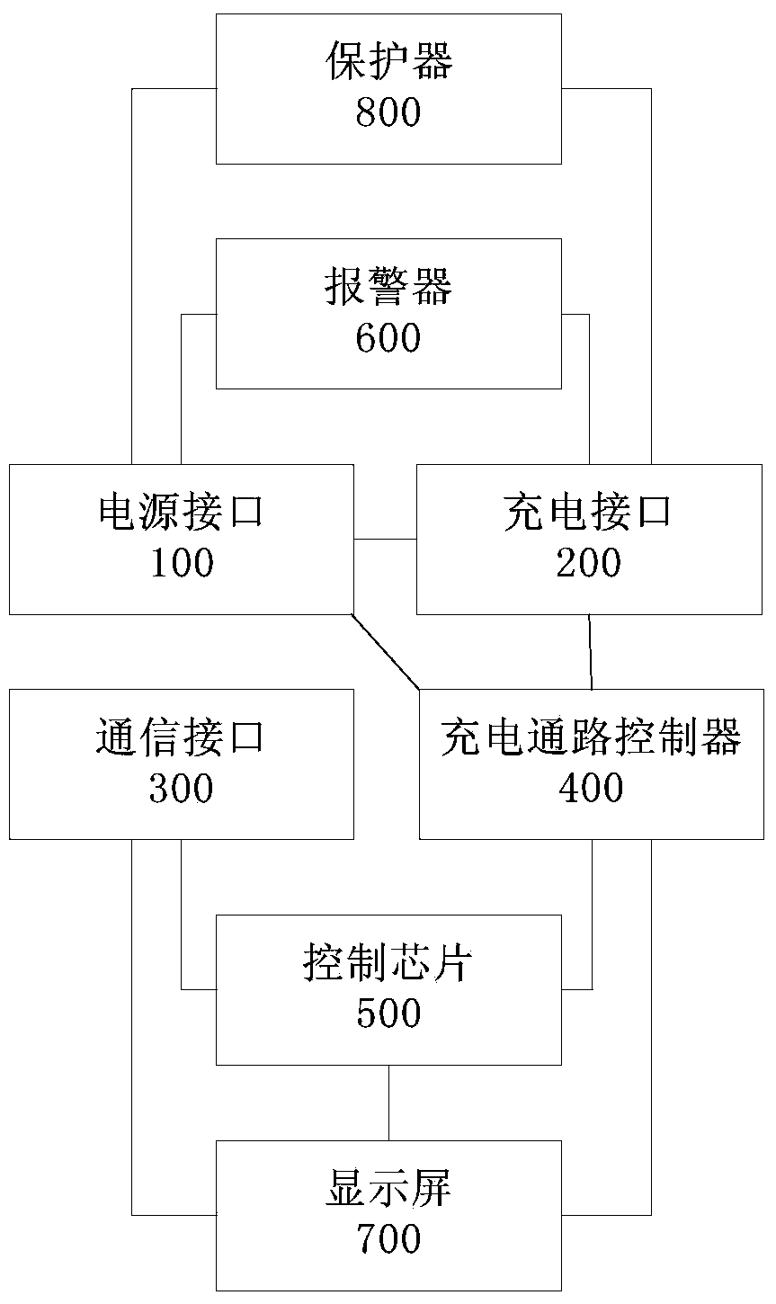
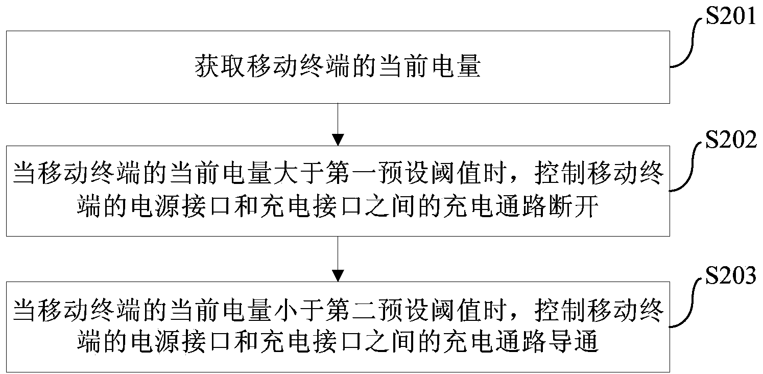
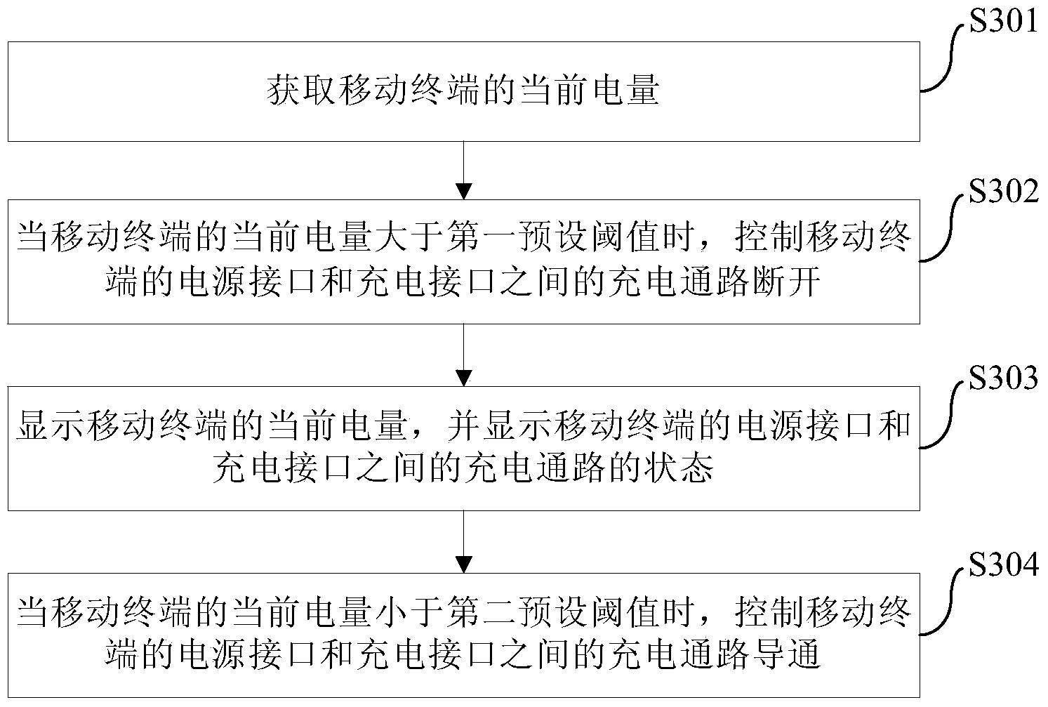
The invention provides a charging system and method of a mobile terminal and a charger. The charger comprises a power interface, a charging interface, a communication interface, a charging path controller and a control chip, wherein the power interface is connected with an external power supply, the charging interface is connected with a charging interface of the mobile terminal, the communication interface is in communication with the mobile terminal and used for acquiring the current electric quantity of the mobile terminal, the charging path controller is connected with the power interface and the charging interface and used for controlling the connection and disconnection of a charging path between the power interface and the charging interface, the control chip is connected with the communication interface and the charging path, and the control chip controls the charging path between the power interface and the charging interface to be disconnected through the charging path controller when the current electric quantity of the mobile terminal is larger than a preset threshold value. The charger has the advantages that loss of a mobile terminal battery is reduced, and the actual service life of the mobile terminal battery is prolonged.

Description

technical field [0001] The invention relates to the technical field of mobile terminal manufacturing, in particular to a charging system, method and charger for a mobile terminal. Background technique [0002] Most lithium batteries adopt a fast charging method, which can quickly fill up about 80% of their electricity, and then convert to a continuous supplementary charging method to continue charging them. However, although lithium batteries can be recharged multiple times, the number of recharges is limited, and the number of rechargeable lithium batteries depends on the charging cycle of the lithium battery. [0003] At present, when a user uses a charger to charge a lithium battery, he needs to manually unplug the charger after the battery is fully charged, so as to stop continuing to charge the lithium battery. In the process of realizing the present invention, the inventor found that the prior art has at least the following problems: if the user forgets to unplug the ...

Claims


Application Information

Patent Timeline
IPC IPC(8): H02J7/00H01M10/44
CPCY02E60/10
Inventor 李鸿韦航李丁盼马健
Owner KENIU NETWORK TECH BEIJING
Why Eureka
Try Eureka