
Solid-liquid mixture filter device

A kind of technology of solid-liquid mixture and filtration device

Inactive Publication Date: 2014-07-30
于洪峰
View PDF2 Cites 1 Cited by
  • Summary
  • Abstract
  • Description
  • Claims
  • Application Information

AI Technical Summary

Problems solved by technology

[0013] 2. It is necessary to rely on the pump to pump the liquid into the filter device for filtration. Since the liquid before filtration is a solid-liquid mixture, it is easy to cause blockage of the pump and wear of the internal parts of the pump.
[0014] 3. The utilization rate of the filter medium is not high, and the filtration efficiency is low
[0015] 4. The filtration precision is low, the highest precision of gravity filtration can only reach 0.06mm, and the highest precision of negative pressure filtration can only reach 0.01mm.
[0016] 5. It is greatly affected by the viscosity of the filtered object, and it cannot filter liquids with high viscosity
[0017] 6. There are many auxiliary equipment, high energy consumption and high maintenance cost
[0018] 7. Disposable filter media pollutes the environment
[0019] 8. Large footprint

Method used


Image

  • Solid-liquid mixture filter device
  • Solid-liquid mixture filter device
  • Solid-liquid mixture filter device

Examples


Embodiment 1

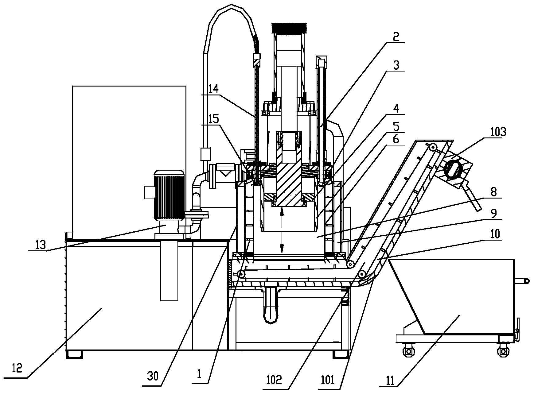
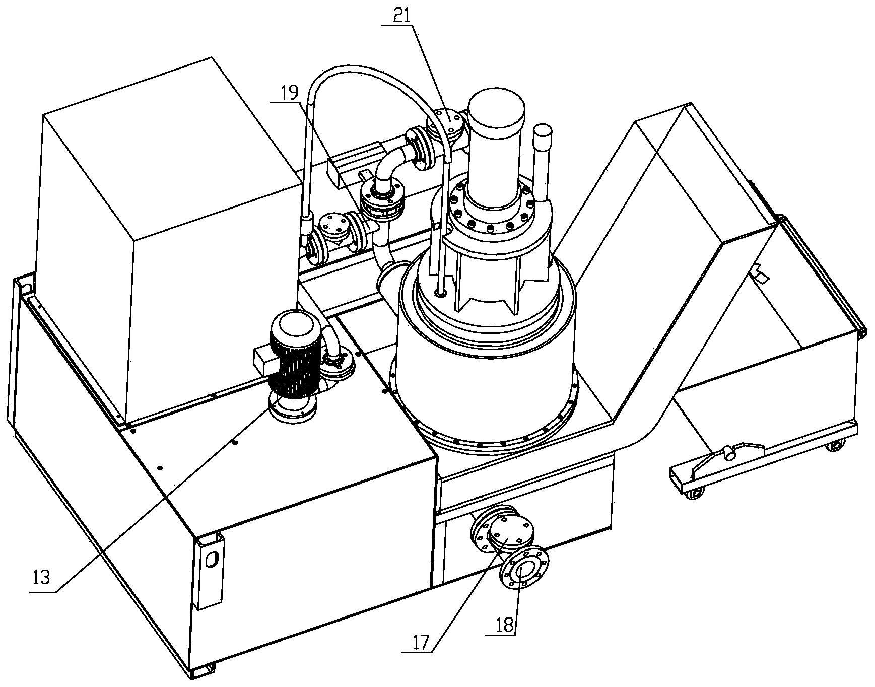
[0056] See attached figure 1 , 2 , a solid-liquid mixture filtering device, comprising a tank 30, a cylinder liner 5, a piston 4, a filter medium 6, and a solid discharge device 10;

[0057] The tank 30 is a hollow sealed cylindrical structure, and the bottom communicates with the solid discharge device 10; a filter medium 6 is arranged in the tank 30, and the filter medium 6 is fixed on the support frame 1 according to the horizontal direction of the tank 30. The cross-sectional shape surrounds a cylinder, which separates the inner space of the tank 30 into two parts: the filter cavity 8 and the clean liquid cavity 9;

[0058] The filter chamber 8 is the space surrounded by the inner wall of the cylinder formed by the filter medium 6, and the clean liquid chamber 9 is the space between the outer wall of the cylinder formed by the filter medium 6 and the inner wall of the tank 30;

[0059] The filter chamber 8 and the clean liquid chamber 9 are communicated through filter ho...

Embodiment 2

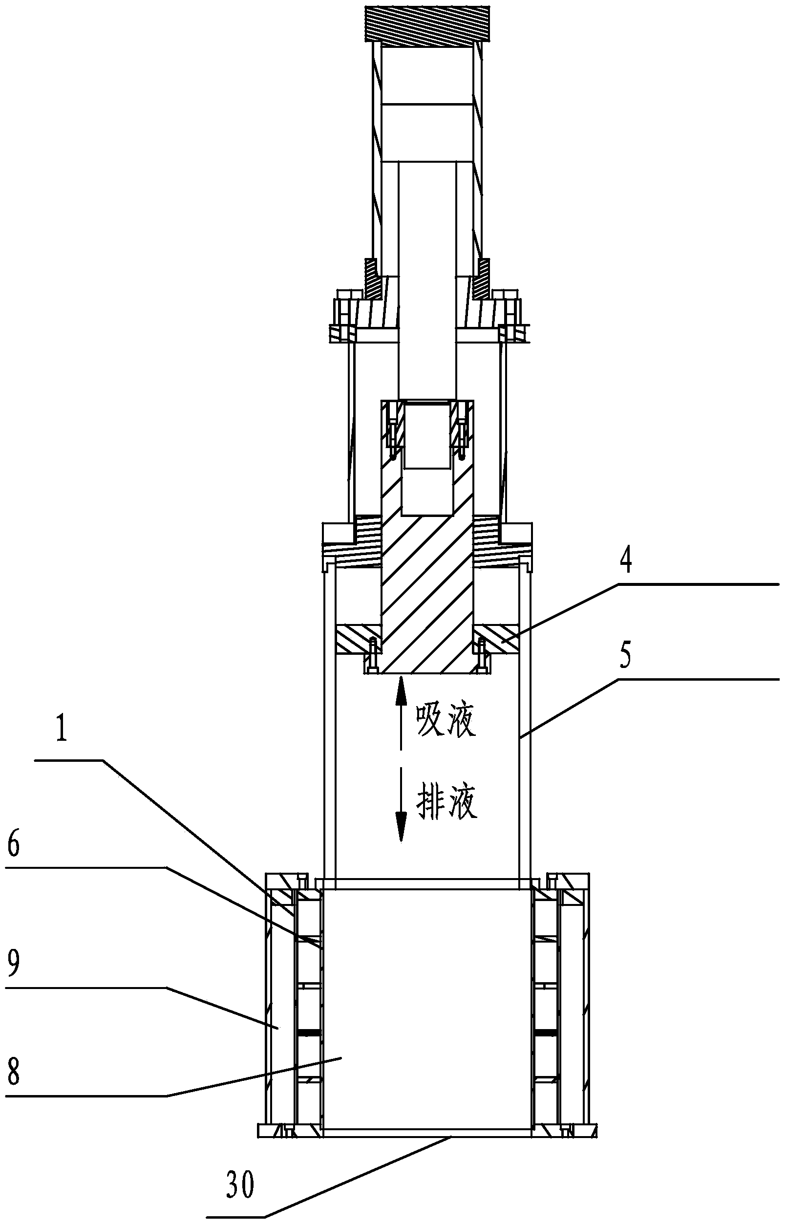
[0073] The difference between this embodiment 2 and embodiment 1 is that the connection and positional relationship between the cylinder liner 5 and the filter cavity 8 in the tank 30 are different;

[0074] See attached image 3 , in this embodiment, the cylinder liner 5 and the filter chamber 8 are coaxially installed on the upper end surface of the filter chamber 8 and communicate with the filter chamber 8 .

Embodiment 3

[0076] The difference between this embodiment 3 and embodiment 2 is that the connection and positional relationship between the cylinder liner 5 and the filter cavity 8 in the tank 30 are different;

[0077] See attached Figure 4 In this embodiment, the 5 sets of cylinders are connected in series on the liquid inlet pipe 18 to communicate with the filter cavity 8; on the liquid inlet pipe 18, there is a The check valve 26 between the filter chambers 8, the cylinder liner 5 is located between the check valve 26 and the liquid inlet check valve 17.


PUM


Abstract

The invention discloses a solid-liquid mixture filter device. The solid-liquid mixture filter device comprises a tank, a cylinder jacket, a piston, a filter medium and a solid discharging device, wherein the bottom of the tank is communicated with the solid discharging device; the filter medium is arranged in the tank; the space in the tank is partitioned into two parts of a filter cavity and a liquid purification cavity; the filter cavity is communicated with the liquid purification cavity through filter holes in the filter medium; a liquid inlet pipe provided with a liquid inlet one-way valve is communicated with the filter cavity; a liquid outlet pipe provided with a liquid outlet one-way valve is arranged on the outer wall of the tank and is communicated with the filter purification cavity; the cylinder jacket is communicated with the filter cavity; the piston is inserted into the cylinder jacket. The solid-liquid mixture filter device is reasonable in structure, convenient to operate, high in filter precision, high in efficiency, low in energy consumption, free from pollution, and low in using cost and maintenance cost, and is applicable to water filter, oil filter and mineral purification and filter, and can be widely applied to filtering of solid-liquid mixtures in water treatment industry, food chemical industry, industrial mining industry, machining industry and the like.

Description

technical field [0001] The invention relates to a solid-liquid mixture filtering device, which belongs to the technical field of solid-liquid separation. Background technique [0002] The current solid-liquid mixture filtration methods are mainly: gravity filtration and negative pressure filtration. [0003] 1. Gravity filtration [0004] The gravity of the liquid is used to push the liquid through the filter medium and enter the clean liquid tank under the filter medium. The typical product of this filtering method is: gravity paper belt filter, which generally adopts a conveyor belt or a mesh belt to support the filter medium at the bottom of the filter chamber, and a net liquid pool is set under the filter medium, and the solid-liquid mixture is pumped. Into the filter cavity, the liquid flows into the net liquid pool through the filter medium under the action of its own gravity, and the solid stays on the filter medium. As the solid accumulates on the filter medium, th...

Claims


Application Information

Patent Timeline
IPC IPC(8): B01D29/35B01D29/64B01D29/68
Inventor 于洪峰
Owner 于洪峰
Learn More