Stirring head for friction stir welding used for welding parts with different thicknesses and welding method

A friction stir welding and stirring head technology, which is applied in welding/welding/cutting items, welding equipment, non-electric welding equipment, etc., can solve the problems of increasing welding difficulty and cost, large impact on joint performance, and high operation control requirements. Guarantee the quality of welded joints, simplify the requirements of equipment and welding methods, and simplify the effect of the welding process

Inactive Publication Date: 2014-07-30
NORTHWESTERN POLYTECHNICAL UNIV
View PDF5 Cites 20 Cited by
  • Summary
  • Abstract
  • Description
  • Claims
  • Application Information

AI Technical Summary

Problems solved by technology

That is to say, the scheme requires the machine head to meet the requirements of adjusting the tilt angle in two directions at the same time, and has higher requirements for welding equipment.
In addition, the conditions of unequal-thickness friction stir welding can also be met by adjusting the tooling, but in many cases, due to the limitations of the part joints and product size, the tooling is not allowed to adjust a certain angle. Therefore, the above-mentioned conventional friction stir welding welding unequal thickness joints In the process of engineering application, there are certain limitations
[0003] Using conventional friction stir welding technology to weld unequal thickness parts requires adjusting the head or tooling of the welding equipment, and at the same time realizes the tilting of the stirring head in the welding direction and two directions perpendicular to the welding direction, which requires high equipment and increases the difficulty of welding. and cost; and in the welding process, it is easy to have insufficient extrusion or shear damage of the shoulder of the stirring head on the metal on the side of the thin plate, and even cause defects or damage to the parts, which has a great impact on the performance of the joint, so it has a great impact on the welding process. The operation control requirements are also high; in addition, when using the traditional friction stir welding technology to weld parts with sudden changes in thickness, it needs to be welded in sections for multiple times to realize the connection of the parts, which is time-consuming and difficult to control

Method used


Image

  • Stirring head for friction stir welding used for welding parts with different thicknesses and welding method
  • Stirring head for friction stir welding used for welding parts with different thicknesses and welding method
  • Stirring head for friction stir welding used for welding parts with different thicknesses and welding method

Examples


Embodiment 1

[0023] Welding 6082 aluminum alloys with different thicknesses, the base metal thicknesses are 5mm and 7mm respectively.

[0024] The diameter of the shaft shoulder of the processing stirring head is Φ12mm, the angle of the cutting auxiliary shaft shoulder is 45°, and the height is 10mm.

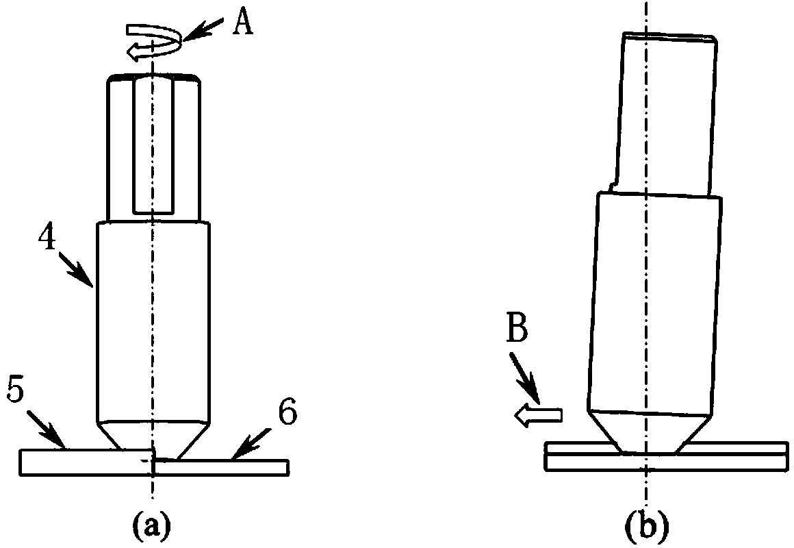
[0025] Welding process: place the stirring head on the welding equipment, and rotate it at 500-1500 rpm, the direction of rotation is counterclockwise, after the shaft shoulder touches the upper surface of the base metal of the thin plate, continue to rotate and stay on the workpiece for 5-10 seconds After that, it is then welded along the seam. The test results show that there is no defect inside the joint, and the fracture positions of the tensile test pieces are all in the heat-affected zone of the friction stir welded joint of the 5mm base metal.

Embodiment 2

[0027] Welding 2024 aluminum alloy with different thickness, the base metal thickness is 2mm and 4mm respectively;

[0028] The diameter of the shaft shoulder of the processing stirring head is Φ10mm, the angle of the cutting auxiliary shaft shoulder is 8°, and the height is 14mm.

[0029] Welding process: place the stirring head on the welding equipment, and rotate it at 800-2000 rpm, the direction of rotation is clockwise, after the shaft shoulder touches the upper surface of the base metal of the thin plate, it will continue to rotate and stay on the workpiece for 3-8 seconds After that, it is then welded along the seam. The test results show that there is no defect inside the surface joint, and the fracture positions of the tensile test pieces are all in the friction stir welded joint on the 2mm base metal side.

Embodiment 3

[0031] Welding 2024 and 6082 aluminum alloys with different thicknesses, the thickness of 2024 aluminum alloy is 4mm, and the thickness of 6082 aluminum alloy is 4.5mm, 5mm, 5.5mm and 6mm respectively.

[0032] The diameter of the shaft shoulder of the processing stirring head is Φ15mm, the angle of the cutting auxiliary shaft shoulder is 70°, and the height is 20mm.

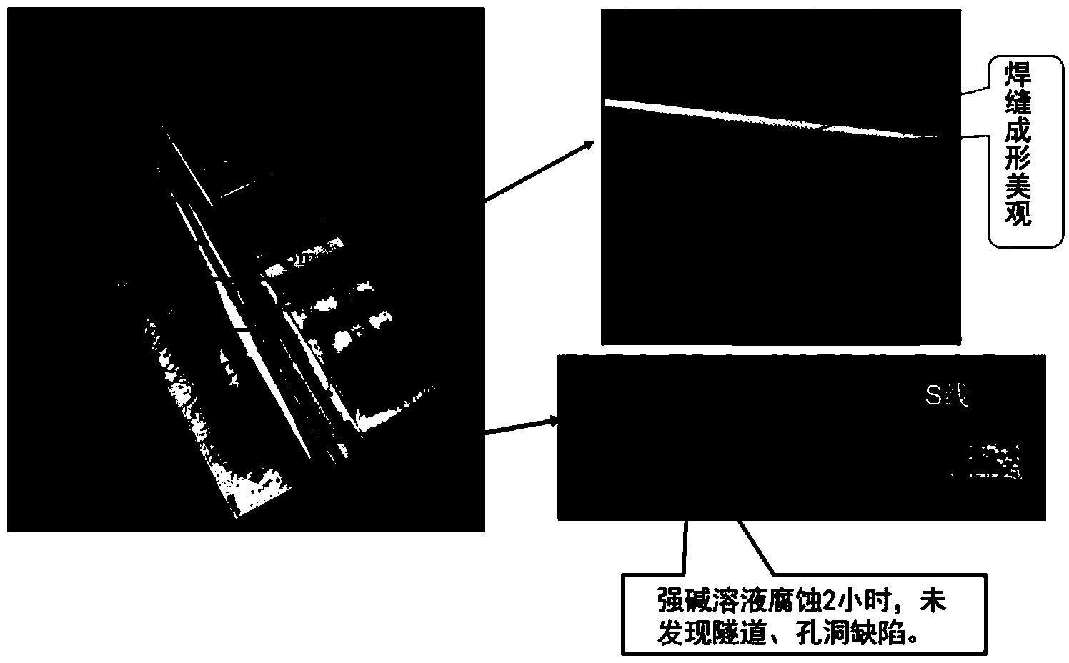
[0033] Welding process: place the stirring head on the welding equipment and rotate it at 600-1000 rpm, the direction of rotation is counterclockwise, after the shaft shoulder touches the upper surface of the 2024 aluminum alloy base material, it will continue to rotate and stay on the workpiece for 5- After 10 seconds, then weld along the seam. The test results show that there are no defects inside the surface joint, and the fracture position of the tensile test piece is at the edge of the friction stir welded joint on the 6082 side. The results are as follows image 3 shown.


PUM


Abstract

The invention relates to a stirring head for friction stir welding used for welding parts with different thicknesses and a welding method. A cutting accessory shaft shoulder is added on the basis of the existing stirring head, and the accessory shaft shoulder plays a role in cutting and removing the redundant material on the thicker side of connectors having different thicknesses to acquire a flat friction stir welding joint. The method is carried out on common friction stir welding equipment, a nose or tool of the equipment is not transformed at all, then the requirements on the equipment and the welding method are greatly simplified; in addition, in the welding process, a shaft shoulder of the stirring head and the two side surfaces of the part are parallel, so that the phenomena that metal of the connector is insufficiently extruded or damaged by shearing are not caused, the integrity and the reliability of the part are guaranteed; moreover, the accessory cutting shaft shoulder of the stirring head also plays an important role as for the part whose thickness suddenly changes, and the smooth welding process of the part is guaranteed.

Description

technical field [0001] The invention belongs to the field of friction stir welding, and relates to a friction stir welding stirring head and a method for welding unequal thickness parts. The stirring head is easy to process and form, the welding method is easy to operate, the joint quality is high, the reliability is good, and it is easy to popularize and apply. Background technique [0002] Friction Stir Welding (FSW for short, US Patent No. 5,460,317) invented by The Welding Institute in the United Kingdom is a solid phase joining technology. This technology provides a new idea for welding problems that are difficult to solve reliably by traditional fusion welding. The problem of unequal thickness welding is a typical case. To weld unequal thickness parts by traditional fusion welding TIG welding, it is necessary to pre-process the joints, that is, process specific grooves according to process requirements. Laser welding welds parts with different thicknesses, and there a...

Claims


Application Information

Patent Timeline
Patent Type & Authority Applications(China)
IPC IPC(8): B23K20/12B23K20/26
CPCB23K20/1255B23K2101/18B23K2103/10
Inventor 李文亚李锦锋张志函高大路王卫兵
Owner NORTHWESTERN POLYTECHNICAL UNIV
Why Eureka
Try Eureka