Step booster exhaust valve

An exhaust valve, high-pressure technology, applied in valve devices, non-mechanically actuated valves, engine components, etc., can solve the problem of invariable exhaust phase and valve lift, high noise of mechanical transmission mechanism, and easy wear and tear of cams. and other problems, to achieve flexible exhaust timing and persistence angle, improve emissions and fuel economy, and achieve the effect of large degrees of freedom

Active Publication Date: 2016-08-03
HARBIN ENG UNIV
View PDF5 Cites 0 Cited by
  • Summary
  • Abstract
  • Description
  • Claims
  • Application Information

AI Technical Summary

Problems solved by technology

The opening and closing time and action rules of the exhaust valve of the existing internal combustion engine are mostly controlled by the cam installed on the camshaft in the timing gear system of the valve train through a set of transmission mechanisms. The cam is easy to wear and tear, and the mechanical transmission mechanism Disadvantages such as high working noise and high machining accuracy requirements, invariable exhaust phase and valve lift, and poor control accuracy

Method used


Image

  • Step booster exhaust valve
  • Step booster exhaust valve

Examples


Embodiment Construction

[0012] The present invention is described in more detail below in conjunction with accompanying drawing example:

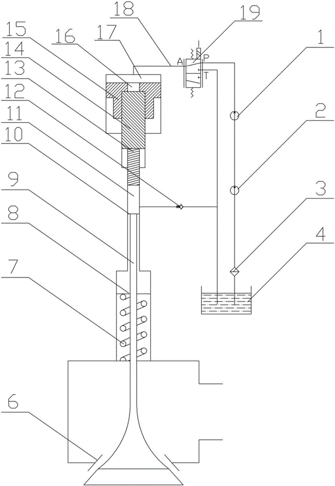
[0013] combine Figure 1~2 , the present invention consists of exhaust valve seat 6, exhaust valve reset spring 7, exhaust valve reset spring seat 8, exhaust valve stem 9, exhaust valve hydraulic piston 10, pressurization chamber 11, hydraulic plunger 13, two The first stage piston 14, the first stage piston 15, the servo oil through hole 16 and the hydraulic chamber 17 are composed. Its features are: a hydraulic cavity 17 is formed between the primary piston 15 and the exhaust valve body, the hydraulic cavity 17 is connected to the high-pressure servo oil pipe 18 through the servo oil inlet, the primary piston 15 is used as the piston sleeve of the secondary piston 14 and the secondary The pistons 14 are connected, and the secondary piston 14 can slide back and forth in the primary piston 15. The primary piston 15 has a servo oil through hole 16, and the servo o...


PUM


Abstract

The object of the present invention is to provide a step-by-step booster exhaust valve, including an exhaust valve seat, an exhaust valve return spring, an exhaust valve return spring seat, an exhaust valve stem, an exhaust valve hydraulic piston, a pressurization chamber, a hydraulic The plunger, the secondary piston, the primary piston, the servo oil through hole and the hydraulic cavity, the hydraulic cavity is formed between the primary piston and the exhaust valve body, the hydraulic cavity is connected with the high-pressure servo oil pipe through the servo oil inlet, the primary piston is connected with the The two-stage pistons are connected, and there is a servo oil through hole on the first-stage piston. The hydraulic plunger is closely connected with the second-stage piston due to the hydraulic pressure of the servo oil in the pressurization chamber, and a pressurization is formed between the hydraulic plunger and the hydraulic piston of the exhaust valve. The pressurization chamber is connected with the servo oil tank through the servo oil suction check valve, and the lower end of the hydraulic piston of the exhaust valve is closely connected with the exhaust valve stem. The invention has a large degree of freedom in the control of the exhaust valve, can flexibly control the exhaust timing and duration angle, can realize the variable lift of the exhaust valve, and can further improve the emission of the internal combustion engine and the fuel economy.

Description

technical field [0001] The invention relates to an engine, in particular to an exhaust valve of the engine. Background technique [0002] During the working process of the internal combustion engine, every time a working cycle is completed, the exhaust gas must be discharged from the cylinder, and the fresh air must be sucked into the cylinder. The intake and exhaust process must be carried out in strict accordance with the timing requirements of the internal combustion engine. The ignition sequence is carried out to ensure that the internal combustion engine operates under optimal conditions. The exhaust valve is one of the important parts of the exhaust system of the internal combustion engine. Its main function is to discharge the burned exhaust gas out of the combustion chamber within a specified time. have a great impact. The opening and closing time and action rules of the exhaust valve of the existing internal combustion engine are mostly controlled by the cam insta...

Claims


Application Information

Patent Timeline
Patent Type & Authority Patents(China)
IPC IPC(8): F01L9/02F01L1/34F01L13/00F01L9/10F01L9/40
Inventor 白云范立云仇会彬连历张建宇马修真费红姿刘晶晶
Owner HARBIN ENG UNIV
Why Eureka
Try Eureka