Two-stage booster valve type exhaust mechanism

A technology of exhaust mechanism and air valve, which is applied in the direction of valve device, mechanical equipment, engine components, etc. It can solve the problems of large working noise of mechanical transmission mechanism, poor control precision of exhaust valve, and easy wear and damage of cam, so as to improve emission And the effect of fuel economy, flexible control, and large degree of freedom

Active Publication Date: 2016-06-29
HARBIN ENG UNIV
View PDF5 Cites 0 Cited by
  • Summary
  • Abstract
  • Description
  • Claims
  • Application Information

AI Technical Summary

Problems solved by technology

The exhaust phase and valve lift of the existing mechanical exhaust system are fixed, which can only guarantee the best performance under a certain working condition, which is unfavorable for internal combustion engines whose working conditions change frequently
Furthermore, due to the use of a mechanical transmission mechanism, there are disadvantages such as easy wear and damage of the cam, high working noise of the mechanical transmission mechanism, high processing precision requirements, and poor control precision of the exhaust valve.

Method used


Image

  • Two-stage booster valve type exhaust mechanism
  • Two-stage booster valve type exhaust mechanism

Examples


Embodiment Construction

[0013] The present invention is described in more detail below in conjunction with accompanying drawing example:

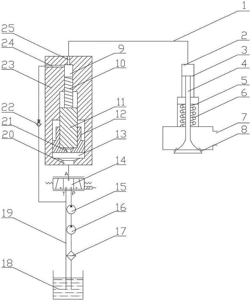
[0014] combine Figure 1~2 , the present invention consists of a hydraulic oil pipe 1, a hydraulic chamber 2, an exhaust valve hydraulic piston 3, an exhaust valve 4, an exhaust valve return spring seat 5, an exhaust valve return spring 6, an exhaust port 7, and an exhaust valve seat 8 , pressurization chamber 9, hydraulic plunger 10, secondary piston 11, primary piston 12, servo oil cavity 13, three-position three-way electromagnetic reversing valve 14, high-pressure servo oil pump 15, servo oil delivery pump 16, servo oil filter Cleaner 17, servo oil tank 18, low pressure servo oil pipe 19, servo oil inlet 20, servo oil through hole 21, servo oil suction check valve 22, booster body 23, low pressure servo oil inlet 24 and servo oil outlet 25. Its features are: a servo oil chamber 13 is formed between the first-stage piston 12 and the supercharger body 23, the s...


PUM


Abstract

The purpose of the present invention is to provide a two-stage pressurized air valve type exhaust mechanism, the opening and closing of the exhaust valve is driven by servo oil hydraulic pressure, and the first-stage piston and the second-stage piston are respectively used to compare the pressure in the pressurization chamber with different pressurization ratios. The servo oil is pressurized to realize different driving pressure control during the opening process of the exhaust valve, and then drives the exhaust valve to open, and controls the PA and AT high-pressure servo oil circuits and low-pressure servo oil through the three-position three-way electromagnetic reversing valve. The on-off of the oil circuit can realize the controllable exhaust timing, exhaust duration angle and exhaust valve lift of the exhaust valve. The invention has simple structure, large degree of freedom in controlling the exhaust valve, can further improve the emission of the internal combustion engine and the fuel economy, and is beneficial to improving the power performance of the internal combustion engine.

Description

technical field [0001] The invention relates to an engine, in particular to an exhaust mechanism of the engine. Background technique [0002] During the working process of the internal combustion engine, every time a working cycle is completed, the exhaust gas must be discharged from the cylinder, and the fresh air must be sucked into the cylinder. The intake and exhaust process must be carried out in strict accordance with the timing requirements of the internal combustion engine. The ignition sequence is carried out to ensure that the internal combustion engine operates under optimal conditions. The exhaust system is an important part of the gas distribution system of the internal combustion engine. Its main function is to discharge the burned exhaust gas out of the combustion chamber within a specified time. have a great impact. The exhaust phase and valve lift of the existing mechanical exhaust system are fixed, which can only ensure the best performance under a certai...

Claims


Application Information

Patent Timeline
Patent Type & Authority Patents(China)
IPC IPC(8): F01L9/02F02B37/00F01L9/10
CPCY02T10/12
Inventor 白云范立云刘鹏许德马修真宋恩哲袁志国董全刘晶晶
Owner HARBIN ENG UNIV
Why Eureka
Try Eureka