A fully variable valve train driven by hydraulic pressure

A valve train, variable technology, applied in the direction of engine components, machines/engines, non-mechanically actuated valves, etc., can solve the problem of small adjustment range, the valve cannot meet the needs of intake, and the valve lift cannot be changed independently and other problems, to achieve the effect of wide adjustment range, improved inflation efficiency, and simple oil circuit design

Active Publication Date: 2020-05-05
JIANGSU UNIV
View PDF8 Cites 0 Cited by
  • Summary
  • Abstract
  • Description
  • Claims
  • Application Information

AI Technical Summary

Problems solved by technology

However, there are some problems. First, the fixed valve lift curve cannot meet the needs of intake air under different working conditions.
The rotor shaft of this mechanism is coaxial with the camshaft, so the adjustment range of the valve closing time is relatively small, and the valve lift cannot be changed independently

Method used


Image

  • A fully variable valve train driven by hydraulic pressure
  • A fully variable valve train driven by hydraulic pressure
  • A fully variable valve train driven by hydraulic pressure

Examples


Embodiment Construction

[0035] The present invention will be further described below with reference to the drawings and specific embodiments, but the protection scope of the present invention is not limited to this.

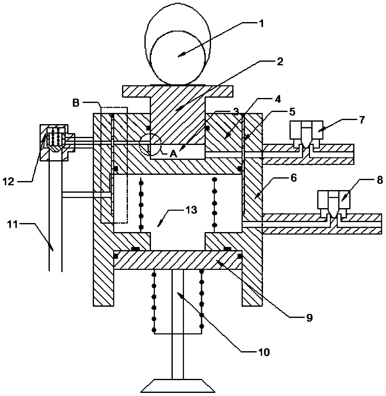
[0036] Such as figure 1 As shown, the hydraulically driven fully variable valve mechanism of the present invention includes a cam 1, a moving boss 2, a hydraulic piston 4, a bushing 5, a housing 6, a second solenoid valve oil unloading assembly 8, a hydraulic Plunger 9, valve 10, high pressure oil source 11 and one-way valve 12.

[0037] Specifically, the shell 6 is provided with a first hole, a second hole, and a third hole that are connected in sequence. The second hole 1301 in the middle has a smaller diameter than the other two through holes. The hydraulic piston 4 and the hydraulic column The plugs 9 are all cylindrical, the inner wall of the first hole is provided with a bushing 5, the hydraulic piston 4 and the bushing 5 are sliding and sealingly fitted, and the hydraulic plunger 9 is...


PUM


Abstract

The invention provides a hydraulically driven fully variable valve mechanism, which includes a cam, a movable boss, a hydraulic piston, a casing, a first solenoid valve unloading control assembly, a hydraulic plunger, an air valve, a high-pressure oil source and a one-way valve , the moving boss is placed in the pressure chamber on the hydraulic piston; changing the oil volume in the pressure chamber can change the height of the moving boss protruding from the top surface of the hydraulic piston, and then change the valve lift, and a hydraulic pressure is formed between the casing, the hydraulic piston and the hydraulic plunger Piston chamber: The hydraulic piston drives the hydraulic oil in the piston chamber to drive the hydraulic plunger to drive the valve movement. By changing the pressure and flow state of the hydraulic oil in the piston chamber, the valve phase can be changed. The invention realizes the fully variable valve timing and lift, and has important significance for improving the economy and emission of the internal combustion engine.

Description

Technical field [0001] The invention relates to the field of engines, in particular to a hydraulically driven fully variable valve mechanism. Background technique [0002] Energy and environmental issues are two important issues facing the automotive industry today. The research and development of low-energy, low-pollution, high-efficiency, energy-saving and environmentally friendly engines is the main direction of engine research and development. Among them, variable valve phase technology has become one of the important technologies to improve engine power and economy. [0003] Traditional engines use a fixed valve lift curve, while adjusting the throttle opening to control the amount of mixed gas entering the cylinder. However, there are problems. First, the fixed valve lift curve cannot meet the needs of intake under different working conditions. The ideal valve phase is to have a small intake late closing angle at low speed and a larger intake late closing angle at high spee...

Claims


Application Information

Patent Timeline
IPC IPC(8): F01L9/02F01L13/00F01L1/344F01L9/10F01L9/40
CPCF01L1/3442F01L13/0015F01L2001/34423F01L2001/3443F01L9/14
Inventor 罗福强徐露罗彤魏胜利邵珊珊
Owner JIANGSU UNIV
Why Eureka
Try Eureka