Oil way structure of cylinder block engine

A technology of cylinder block and oil circuit, applied in the direction of cylinder, cylinder head, mechanical equipment, etc., can solve the problems of many engine through pipelines, high engine cost, large size of the whole machine, etc. High matching effect

Pending Publication Date: 2020-07-14
GUANGXI YUCHAI MASCH CO LTD
View PDF0 Cites 0 Cited by
  • Summary
  • Abstract
  • Description
  • Claims
  • Application Information

AI Technical Summary

Problems solved by technology

[0005] 2. Parts with different functions are designed separately, and the cost is high
The oil inlet and outlet pipelines are externally designed, the engine runs through many pipelines, the appearance is messy, the overall size is large, and the engine cost is high

Method used


Image

  • Oil way structure of cylinder block engine
  • Oil way structure of cylinder block engine

Examples


Embodiment 1

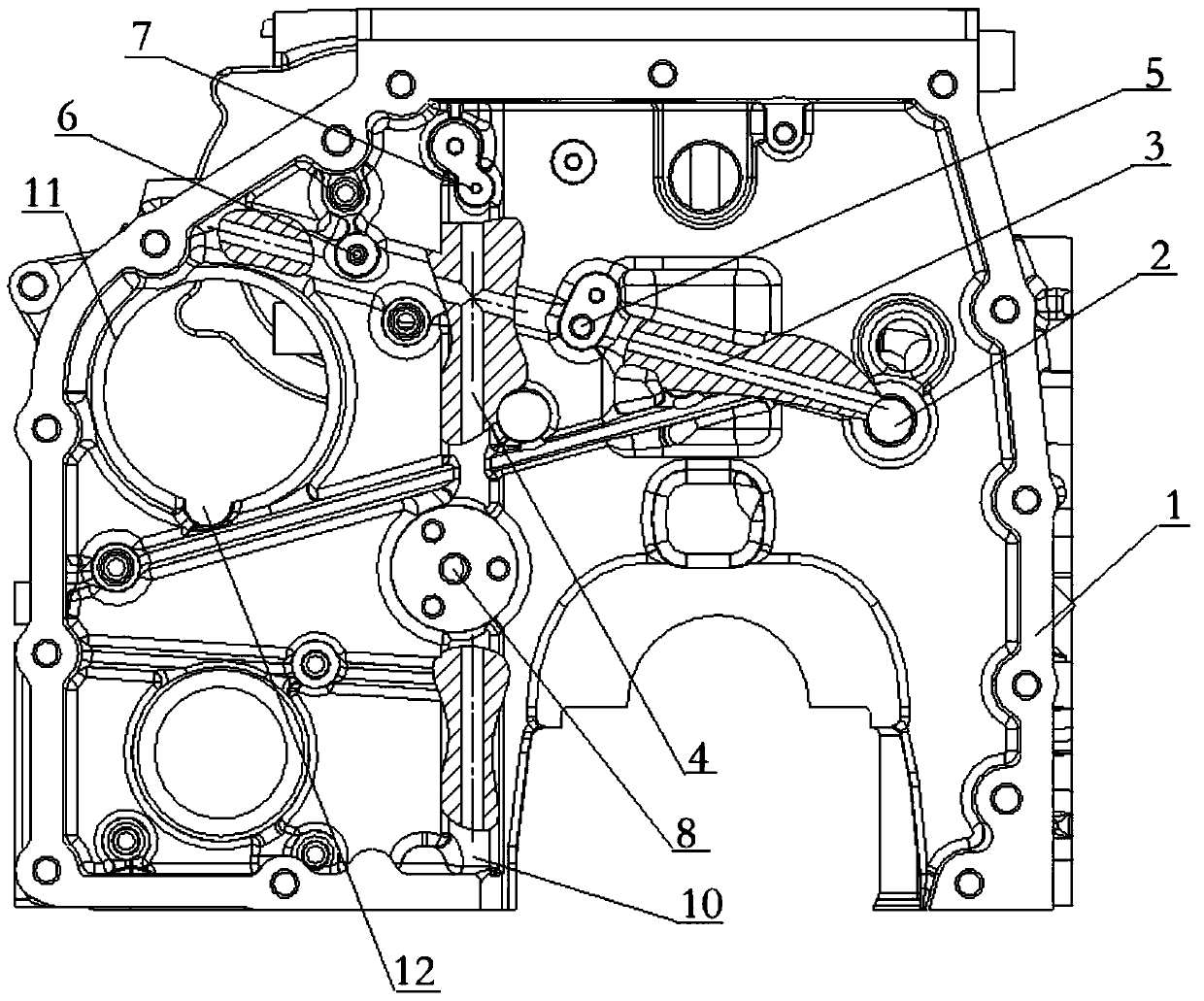
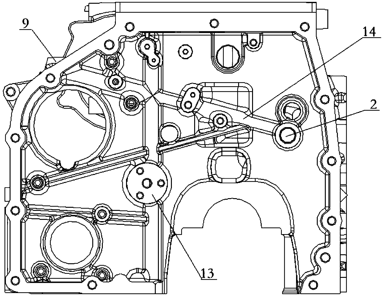
[0028] See also figure 1 and figure 2 , The embodiment of the present invention provides a cylinder block engine oil passage structure, including a main oil passage 2 arranged on the exhaust side of the engine and passing through the front and rear ends of the cylinder block 1 . The present invention also includes a transverse oil passage 3 and a longitudinal oil passage 4 arranged inside the gear chamber at the rear end of the cylinder block 1 . The right end of the horizontal oil passage 3 communicates with the main oil passage 2, and the left end spans the bottom of the gear chamber and communicates with the oil port 5 of the chain lubricating injection valve and the oil port 6 of the air pump respectively. The longitudinal oil passage 4 runs through the transverse oil passage 3, and the longitudinal oil passage 4 communicates with the oil port 7 of the chain tensioner and the lubricating oil port 8 of the idler shaft respectively.

[0029] When the oil passage structure...

Embodiment 2

[0036] In this embodiment, except that the installation positions of the lubricating oil port of the air pump and the oil port of the chain tensioner are different, everything else is the same as that of Embodiment 1.

[0037] In this embodiment, the installation positions of the lubricating oil port of the air pump and the oil port of the chain tensioner are reversed. Specifically, one end of the horizontal oil passage is connected to the main oil passage, and the other end spans the bottom of the gear chamber and is respectively connected to the oil port of the chain lubricating injection valve and the oil port of the chain tensioner. The longitudinal oil passage runs through the transverse oil passage, and the longitudinal oil passage is respectively connected to the lubricating oil port of the air pump and the lubricating oil port of the idler shaft.


PUM


Abstract

The invention discloses an oil way structure of a cylinder block engine. The oil way structure comprises a main oil way arranged on the exhaust side of the engine and penetrating through the front endand the rear end of a cylinder block, and further comprises a transverse oil way and a longitudinal oil way which are arranged in a gear chamber at the rear end of the cylinder block. One end of thetransverse oil way communicates with the main oil way, and the other end of the transverse oil way stretches across the gear chamber and communicates with a chain lubricating injection valve oil portand an air pump lubricating oil port. The longitudinal oil way penetrates through the transverse oil way and communicates with a chain tensioner oil port and an idler shaft lubricating oil port. According to the oil way structure, the functions of lubricating and the like of all functional parts are achieved at the same time, the design of the oil way of a lubricating system is simplified, the oilway structure is arranged in the gear chamber at the rear end of the cylinder block, the oil ways are staggered longitudinally and transversely, oil way walls serve as cylinder block reinforcing ribs, the overall structural strength of the cylinder block is obviously enhanced, and the structural strength of the cylinder block is improved.

Description

technical field [0001] The invention relates to the technical field of engines, in particular to a cylinder block engine oil circuit structure. Background technique [0002] When designing the layout of light-duty engines, it is necessary to arrange various necessary functional parts in a limited space. Especially in the implementation stage of the National VI emission regulations, more functional parts need to be added to the engine design. higher requirement. [0003] The main problems encountered during the layout process are as follows: [0004] 1. For a light-duty engine, the matching cabin is relatively small, and the engine needs to match one of the functions, and the layout and design space of each functional part is very limited; [0005] 2. Parts with different functions are designed separately, and the cost is high. [0006] Therefore, it is necessary to consider multi-functional integrated design as much as possible in the engine layout design under the premis...

Claims


Application Information

Patent Timeline
Patent Type & Authority Applications(China)
IPC IPC(8): F02F1/20F01M1/08F01M1/12
CPCF01M1/08F01M1/12F02F1/20
Inventor 覃海玉曾德林董家枝
Owner GUANGXI YUCHAI MASCH CO LTD
Why Eureka
Try Eureka