
Vacuum sucker

A vacuum suction cup and height-adjusting technology, applied in suction cups, connecting components, household components, etc., can solve the problems of high adsorption force and easy falling off, high processing accuracy requirements, affecting the yield of finished products, etc., and achieves long service life and improved processing accuracy. , easy-to-create effects

Active Publication Date: 2014-07-30
浙江西塘实业有限公司
View PDF6 Cites 5 Cited by
  • Summary
  • Abstract
  • Description
  • Claims
  • Application Information

AI Technical Summary

Problems solved by technology

But because the elastic card is installed horizontally and pushed horizontally, the adsorption force of the adsorption plate is not the largest and it is easy to fall off. At the same time, because it is not easy to disassemble, if it fails to pass the test after installation, it will be scrapped, which will directly affect the yield.
[0004] Although the patent application number 201310528802.5 "vacuum suction cup" also discloses that there is a height adjustment piece between the cover and the suction piece that can adjust the height of the suction piece, and the pressure seat and the stopper that can adjust the height of the height adjustment piece are tightly pressed between the height adjustment piece and the suction piece. Take off the ring, turn the cover to lift the adsorption sheet, and create a vacuum between the adsorption sheet and the adsorption surface, but the structure of each component is complicated and difficult to process, requiring high processing accuracy, and installation is troublesome

Method used


Image

  • Vacuum sucker
  • Vacuum sucker
  • Vacuum sucker

Examples


Embodiment Construction

[0019] Embodiments of the present invention will be further described below in conjunction with the accompanying drawings.

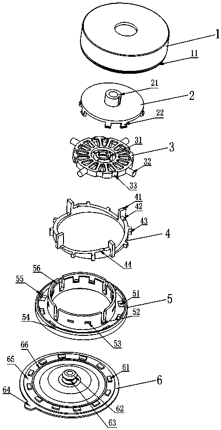
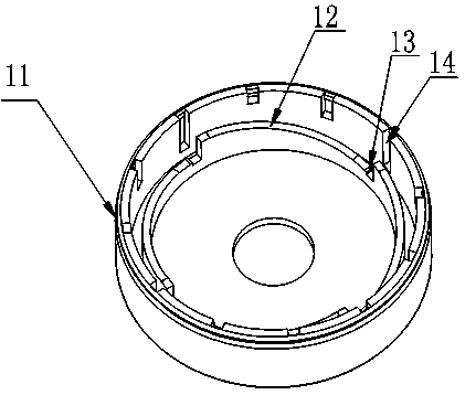
[0020] On the periphery of the inner wall of the cover 1, concave positioning ribs 14 uniformly distributed and of different heights are arranged, a ring groove 11 is arranged on the outer periphery of the lower edge, a through hole is arranged in the middle of the top surface, and there are more than two evenly distributed reverse ribs on the inner wall of the top surface. The annular circular wall formed by the slope 12 has a gap with the inner wall of the cover, and is matched with the forward slope 44 on the guide ring 4 directly below.

[0021] There is a connector 21 in the middle of the circular upper surface of the connecting seat 2, which is connected with the pendant (not shown in the figure), and there are hooks 22 extending out from the circular outer periphery and facing downwards, symmetrically distributed.

[0022] The upper surface of the...


PUM


Abstract

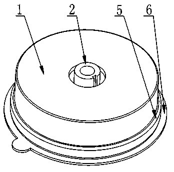
A vacuum sucker comprises a cover, a compressing seat, a height adjustment piece and a suction wrapper which are connected into a whole, wherein the upper end and the lower end of the compressing seat are connected with a connecting seat and the suction wrapper; the inner side and the outer side of the compressing seat are connected with the height adjustment piece and a guide ring; the guide ring is matched with the height adjustment piece to allow the height adjustment piece to drive the suction wrapper to move upwards; a hanger is mounted on the connecting seat; a center pole on the suction wrapper is connected with the height adjustment piece into a whole; and the cover is connected with the compressing seat into a whole.The parts forming the sucker are concentric independent pieces; the sucker is simple in structure, easy to manufacture and high in precision; the compressing seat serves as a foundation; the parts are buckled and mounted on the compressing seat; stripping and air leakage affecting a use effect and an adsorption force do not happen; the outer side of the compressing seat is sleeved with the guide ring; the guide ring is matched with the height adjustment piece, so that a stress scope of the suction wrapper is moved to a peripheral plane from the middle; a vacuum space and the adsorption force are greatly extended and increased; and the sucker can be absorbed on an absorption surface without falling for a long time.The center pole connected with the hanger is divided into two independent parts, and the hanger is not directly fixed at the middle part of the suction wrapper, so that the sucker is good in use effect, long in service life and more practical, and the adsorption force can be increased by 20%.

Description

technical field [0001] The invention relates to a suction plate, in particular to a vacuum suction plate connected with a pendant for hanging towels, bath towels, clothes and the like. Background technique [0002] The existing suction cup hooks are composed of a suction cup and a pendant. The suction cup needs to be adsorbed on a flat, smooth glass, ceramic tile, etc. If the adsorption force between the adsorption surface and the suction sheet on the suction cup is not enough, the suction cup will easily fall off and affect the use effect. Bring a lot of inconvenience to the user. [0003] Patent No. 201010151121.8 "Vacuum Adsorber" provides a vacuum suction cup, which is installed between the cover and the adsorption plate to move the adsorption plate up or down with the rotation of the cover, and a height adjustment accessory with an elastic card fixed on it. The elastic card passes through the cover when it is turned. The fixed plate installed on the inner wall of the c...

Claims


Application Information

Patent Timeline
IPC IPC(8): F16B47/00A47G29/087
Inventor 沈琳琳
Owner 浙江西塘实业有限公司
Learn More