Control valve group of hydraulic clutch

A technology of hydraulic clutches and control valves, applied in clutches, lubricating oil control valves, fluid-driven clutches, etc., can solve problems such as large heat generation, and achieve good lubrication and small fluctuations

Active Publication Date: 2014-07-30
NANJING HIGH ACCURATE MARINE EQUIP CO LTD
View PDF4 Cites 2 Cited by
  • Summary
  • Abstract
  • Description
  • Claims
  • Application Information

AI Technical Summary

Problems solved by technology

[0003] The purpose of the present invention is to solve the problem that the existing control method of the hydraulic clutch generates a lot of heat during the operation of the system, and it cannot satisfy the flow requirements of the system during normal operation, and at the same time, perform good lubrication and cooling on other parts of the full rotation, etc. A series of problems to provide a new hydraulic clutch control valve group

Method used


Image

  • Control valve group of hydraulic clutch
  • Control valve group of hydraulic clutch
  • Control valve group of hydraulic clutch

Examples


Embodiment Construction

[0020] The accompanying drawings disclose the specific structures of the embodiments of the present invention without limitation, and the present invention will be further described below in conjunction with the accompanying drawings.

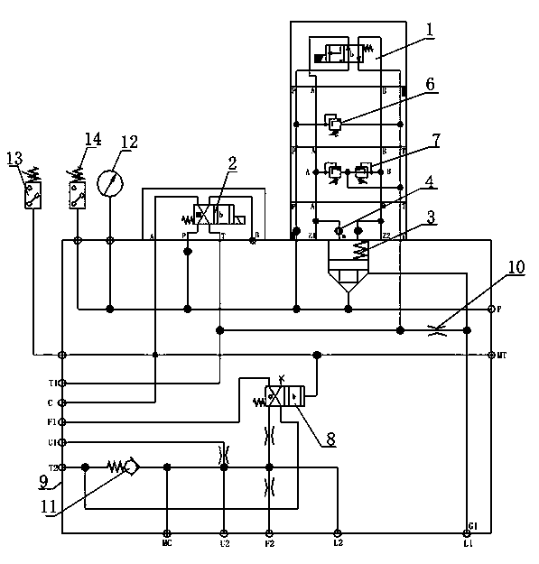
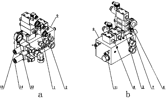
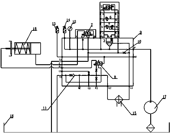
[0021] Depend on figure 1 figure 2 It can be seen that the present invention includes a valve body 9, a functional valve core is installed on the valve body 9, and an interface is provided, and an oil passage is provided in the valve body 9, wherein:

[0022] The functional spool includes a first electromagnetic reversing valve 1, a second electromagnetic reversing valve 2, a P port relief valve 6, an AB port relief valve 7, a hydraulic control reversing valve 8, a cartridge valve 3 and a single To the valve 11;

[0023] The ports on the valve body include: high pressure input port P, hydraulic clutch drive port C, hydraulic clutch lubrication port F 1 , the oil return port T of the function spool 1 , lubricating oil return port T ...


PUM


Abstract

The invention discloses a control valve group of a hydraulic clutch. The control valve group comprises a valve body, wherein a functional valve core is mounted on the valve body; the valve body is provided with connection openings; an oil duct is arranged in the valve body; the functional valve core comprises a first electromagnetic exchange valve, a second electromagnetic exchange valve, a P opening overflow valve, an AB opening overflow valve, a pilot operated directional control valve, an inserting valve and a one-way valve; the connection openings comprise a high voltage input opening P, a hydraulic clutch driving connection opening C, a hydraulic clutch lubricating connection opening F1, a functional valve core oil return opening T1, a lubricant passage way oil return opening T2, a cooler oil inlet connection opening L1 and a cooler oil outlet connection opening L2. The control valve group can meet the flow requirement of a system during normal operation, meanwhile can obtain more lubricant, properly lubricates the fully rotating control valve group and other parts, guarantees certain operating pressure in a lubricant passage way, balances oil pressure in all oil ducts, ensures that the fluctuation is relatively small, and simultaneously and effectively cools the system while lubricating the system.

Description

technical field [0001] The invention relates to a clutch pressure control valve group, in particular to a control valve group for a hydraulic clutch of a full-turn hydraulic clutch. Background technique [0002] The hydraulic clutch is a common clutch. When the pressure oil enters the clutch cylinder, the piston presses the friction disc against the baffle, so that the clutch produces frictional engagement. Once the pressure is reduced, the return spring resets the piston, so that the clutch is disengaged. Controlling the on-off of the hydraulic oil can control the engagement and disengagement of the clutch. At present, most hydraulic clutches use a relief valve and a reversing valve to control the working pressure of the clutch and the engagement and disengagement of the clutch. Some clutches also require A separate system cools and lubricates the clutch. In this commonly used system, the relief valve can only set one working pressure. Therefore, regardless of whether the ...

Claims


Application Information

Patent Timeline
Patent Type & Authority Applications(China)
IPC IPC(8): F16D25/12F16N23/00
Inventor 舒永东常晓雷王国军刘光平刘伟杜鹏李祥彪常江
Owner NANJING HIGH ACCURATE MARINE EQUIP CO LTD
Why Eureka
Try Eureka