LED (light emitting diode) driving power supply large chip

An LED driver and LED chip technology, applied in the field of LED lighting, can solve the problems of inability to place opto-mechanical modules, difficult LED driver power miniaturization, light weight and transparency, etc., to reduce complexity, small size, and easy to standardize Effect

Active Publication Date: 2014-07-30
GUIZHOU GUANGPUSEN PHOTOELECTRIC
View PDF10 Cites 36 Cited by
  • Summary
  • Abstract
  • Description
  • Claims
  • Application Information

AI Technical Summary

Problems solved by technology

This idea makes it difficult to miniaturize, lighten and transparent the LED drive power supply, and it cannot be placed in the optical-mechanical module, and ultimately it cannot be directly connected to the mains power in general-purpose and interchangeable LED bulbs.

Method used


Image

  • LED (light emitting diode) driving power supply large chip
  • LED (light emitting diode) driving power supply large chip
  • LED (light emitting diode) driving power supply large chip

Examples


Embodiment Construction

[0039] The present invention will be further described below in conjunction with the accompanying drawings and embodiments, but not as a basis for limiting the present invention.

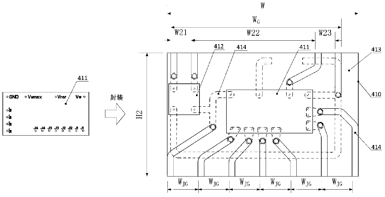
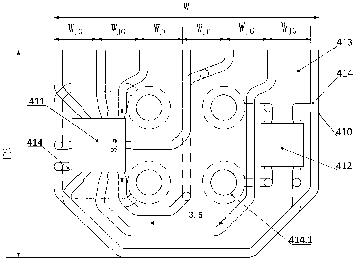
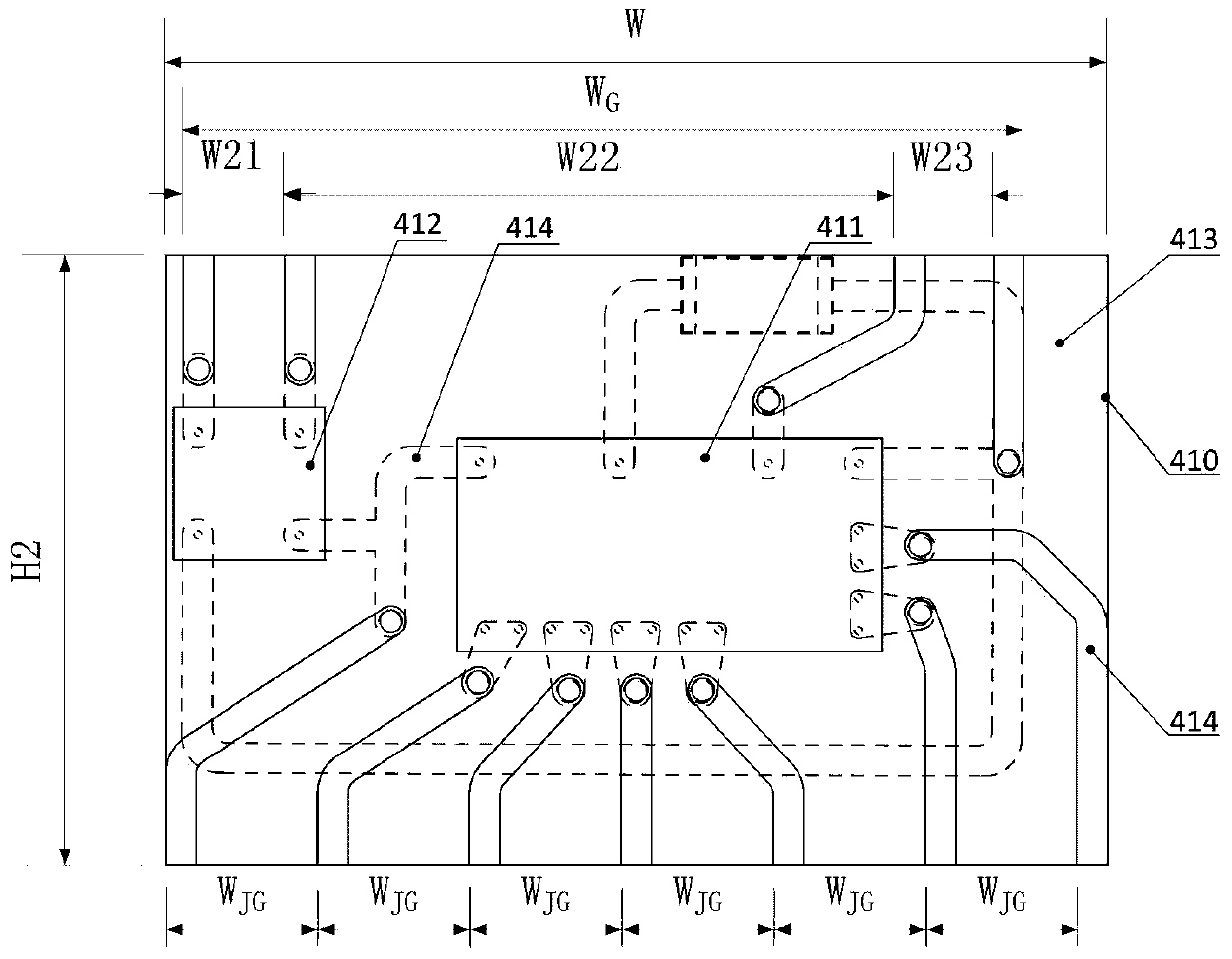
[0040] Example. Large chip of LED driving power supply: including a second transparent substrate 413 with a fixed width of W, the second transparent substrate 413 is printed with a silver paste circuit, an interface wire is formed on the silver paste circuit, and the interface wire has an input end and an output end; The width of the input end and the width W of the lead access end of the optomechanical template 43 G The same or have a pad connected to the electrical connector; there are N+1 parallel interface wires on the silver paste circuit at the output end, and the distance between two adjacent interface wires is W JG It is equal to W minus the interface wire width and then divided by N(W JG =(W-interface wire width) / N); On the second transparent substrate 413, first stick unpackaged power dr...


PUM


Abstract

The invention discloses an LED (light emitting diode) driving power supply large chip, which comprises transparent base plates (413) with the width constantly being W, wherein a second transparent base plate (413) is printed with a silver slurry circuit, and an interface conducting wire is formed on the silver slurry circuit and is provided with an input end and an output end; the width of the input end is identical to the width WG of a conducting wire input end of a light machine template (43), or the input end is provided with a welding disc connected with an electric connector; N+1 parallel interface conducting wires are arranged on the silver slurry circuit arranged at the output end, and the space WJG of the two adjacent interface conducting wires can be obtained through dividing the difference value of W and the width of the interface conducting wire by N; an unencapsulated power supply driving wafer level chip (411) and a rectifier bridge wafer level chip (412) are firstly pasted on the second transparent base plate (413), and then, the unencapsulated power supply driving wafer level chip (411) and the rectifier bridge wafer level chip (412) are welded onto the second transparent base plate (413).

Description

technical field [0001] The invention relates to a large chip of an LED driving power supply, belonging to the technical field of LED lighting. Background technique [0002] Application Nos. 201310140124.5, 201310140138.7, 201310140150.8, 201310140105.2, 201310140134.9, 201310140106.7, 201310140151.2, 201310140151.2, 201310140136.8 and other Chinese patent applications for the common technology of light bulb group interchangeable with multiple LED modules and 201310140136.8. These technologies have laid the foundation for the establishment of a lighting industry structure centered on LED bulbs, and the basic concept of making LED bulbs (lighting sources), lamps, and lighting controls independent production and application of end products. However, the above-mentioned patents have not yet solved the problem of the built-in drive power of the optomechanical module. [0003] The current LED drive power supply is mostly a switching power supply, which is too large; there are als...

Claims


Application Information

Patent Timeline
Patent Type & Authority Applications(China)
IPC IPC(8): F21V23/00H01L25/16F21Y101/02F21Y115/10
Inventor 张继强张哲源朱晓冬
Owner GUIZHOU GUANGPUSEN PHOTOELECTRIC
Why Eureka
Try Eureka