Burning-out air and secondary air adjusting device of pulverized coal boiler
A pulverized coal boiler and regulating device technology, which is applied in the direction of combustion equipment, lighting and heating equipment, etc., can solve the problems of insufficient rigidity of the jet, and achieve the effects of simple structure, delay mixing, and promotion of mixing disturbance
- Summary
- Abstract
- Description
- Claims
- Application Information
AI Technical Summary
Problems solved by technology
Method used
Image
Examples
specific Embodiment approach 1
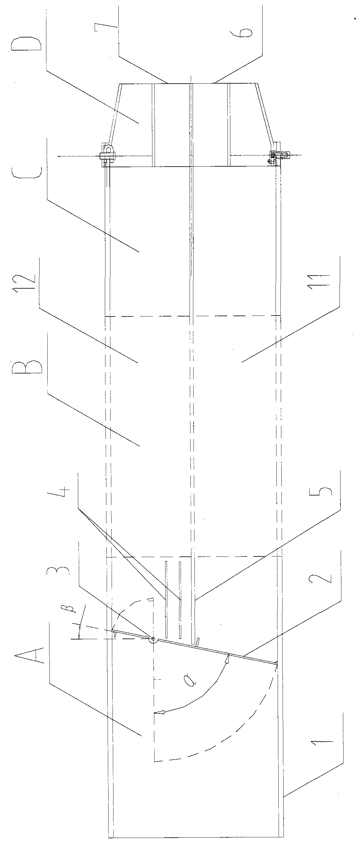
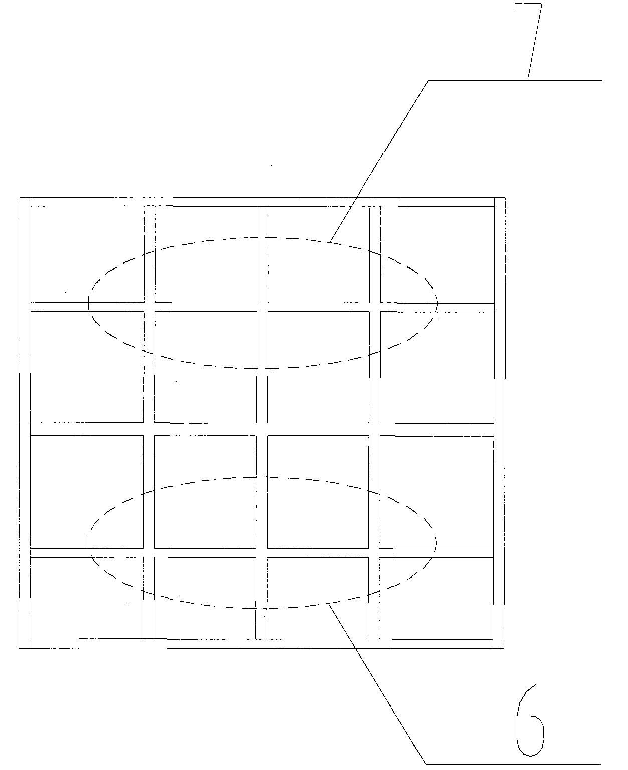
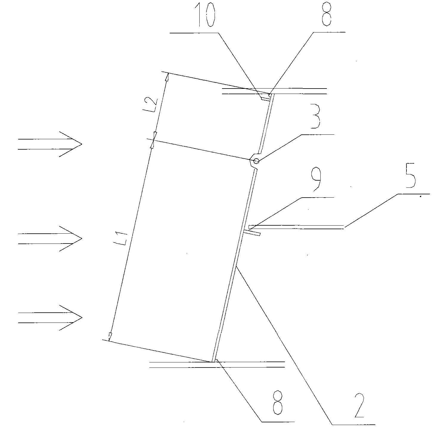
[0010] Specific implementation mode one: combine figure 1 , figure 2 , image 3 This embodiment will be described. This embodiment includes a main air duct 1, an adjustment baffle 2, a rotating shaft 3, a partition 5, a high wind speed nozzle 6, a low wind speed nozzle 7, and the like. The clapboard 5 divides the main air duct 1 into a high-speed air duct 11 and a low-speed air duct 12. An eccentric adjustment baffle 2 is arranged in the main air duct in front of the clapboard. The rotating shaft 3 of the adjusting baffle is on one side of the low-speed air duct, and a group of small baffles 4 are arranged in the low-speed air duct 12 behind the baffle, and the different parts of the baffle 2 are respectively provided with high-speed small baffles 9 and low-speed small baffles. plate 10. The outlet of the high-speed air channel 11 is provided with a high-speed nozzle 6, and the outlet of the low-speed air channel 12 is provided with a low-speed nozzle 7.
specific Embodiment approach 2
[0011] Specific implementation mode two: combination figure 1 and Figure 5 To illustrate this embodiment, the device mainly includes A zone, B zone, C zone, and D zone. Among them, area A (the damper baffle control section) is mainly for air volume distribution, area B (connection section) is the connection section from the bellows to the nozzle, which can be a straight connection section or a curved connection section, and area C is the straight section before the nozzle , area D is the nozzle section.
specific Embodiment approach 3
[0012] Specific implementation mode three: combination figure 1 , figure 2 , image 3 and Figure 4 To illustrate this embodiment, the partition plate 5 divides the main air passage 1 into a high-speed air passage 11 and a low-speed air passage 12, and the area ratio between the high-speed passage 11 and the low-speed passage 12 is 4:6 to 6:4. The rotating shaft 3 is arranged on one side of the low-speed air duct. The adjusting baffle plate 2 is divided into two parts, long and short, by the rotating shaft 3, and the ratio of the two is 2:1 to 3.5:1. When the air door adjustment baffle is in the fully closed state, the adjustment baffle 2 is arranged obliquely in the air duct, the short side of the adjustment baffle is inclined towards the low-speed air duct side, and the inclination angle β is 6° to 15°, and the limit Plate 8 is limited. At the same time, small baffles are set on different parts of the adjustment baffle 2, wherein the high-speed small baffle 9 is locate...
PUM
 Abstract
Description
Claims
Application Information
 - R&D
- Intellectual Property
- Life Sciences
- Materials
- Tech Scout
- Unparalleled Data Quality
- Higher Quality Content
- 60% Fewer Hallucinations
Browse by: Latest US Patents, China's latest patents, Technical Efficacy Thesaurus, Application Domain, Technology Topic, Popular Technical Reports.
© 2025 PatSnap. All rights reserved.Legal|Privacy policy|Modern Slavery Act Transparency Statement|Sitemap|About US| Contact US: help@patsnap.com


