Heat pipe and heat exchanger adopting same

A heat pipe and heat exchange part technology is applied in the field of heat pipes and heat exchangers having the heat pipes, which can solve the problems that fluids cannot flow and integrate well, affect heat exchange efficiency, increase heat exchange efficiency, etc., and save production materials. , the effect of improving heat transfer efficiency, increasing porosity and heat transfer area

Inactive Publication Date: 2014-07-30
KUN SHAN DOTOP METAL TECH CO LTD
View PDF5 Cites 1 Cited by
  • Summary
  • Abstract
  • Description
  • Claims
  • Application Information

AI Technical Summary

Problems solved by technology

[0005] However, the patent separates the channels, and the fluid between the channels cannot flow and fuse well, which affects the heat exchange efficiency. At the same time, there is no functional layer on the inner wall of the heat pipe that can effectively increase the heat exchange efficiency.

Method used


Image

  • Heat pipe and heat exchanger adopting same
  • Heat pipe and heat exchanger adopting same
  • Heat pipe and heat exchanger adopting same

Examples


Embodiment 1

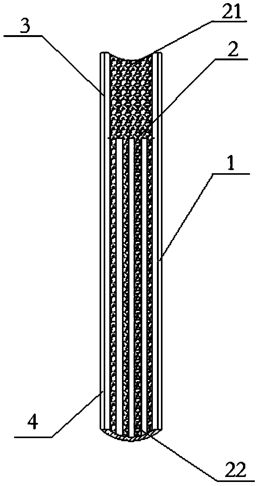
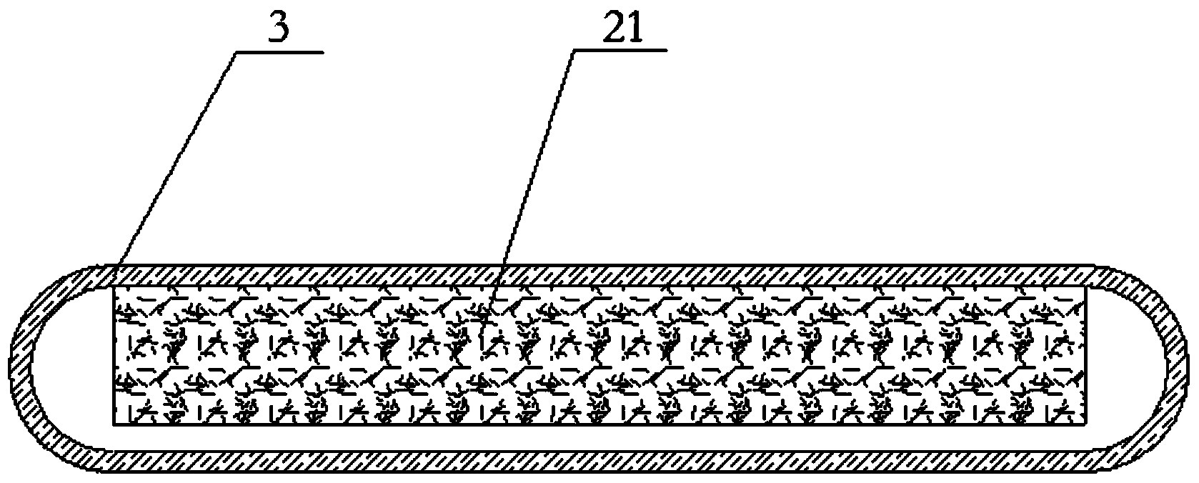
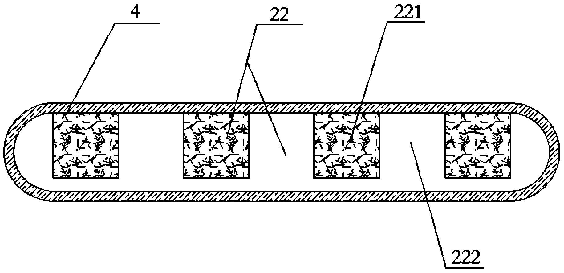
[0029] Such as Figure 1-3 Shown is a heat pipe proposed in this embodiment, which includes a tube body 1 having a flat cross-sectional shape, and two ends of the tube body 1 are respectively an evaporation section 3 and a condensation section 4 . The height between the upper wall and the lower wall of the tubular body 1 is 1.2mm-1.5mm; the width of the tubular body 1 is 8.3mm-8.5mm; the thickness of the upper wall and the lower wall of the tubular body 1 is 0.15mm-0.2mm. As a preferred embodiment, the cross section of the pipe body 1 is an oblong cross section or a rectangular cross section.

[0030] A sintered capillary structure 2 is provided on the inner surface of the upper or lower wall of the cross section, the sintered capillary structure 2 extends along the axial direction of the tube body 1, and the width of the sintered capillary structure 2 is 5.0mm- 5.5mm. In the process of forming the pipe body 1, copper pipes with an inner diameter of 5 mm, 6 mm or 8 mm and a...

Embodiment 2

[0035] This embodiment proposes a heat exchanger, and the heat pipe as described in Embodiment 1 is arranged inside the heat exchanger. The heat exchanger in this embodiment is made of the heat pipe in Embodiment 1. The heat pipe wall is thinner, which improves the heat transfer efficiency, enhances the heat conductivity of the heat exchanger, and reduces the production cost of the heat exchanger.


PUM


Abstract

The invention relates to the technical field of heat-exchanging devices, and discloses a heat pipe and a heat exchanger adopting the same. The heat pipe comprises a pipe body, wherein the cross section of the pipe body takes a tabular shape; the two ends of the pipe body are an evaporation section and a condensation section respectively; a sintering capillary structure is arranged on the inner surface of the upper wall or the lower wall of the cross section of the pipe body; the sintering capillary structure extends in the axial direction of the pipe body and comprises a first heat-exchanging part; the first heat-exchanging part is arranged on the condensation section of the pipe body; the first heat-exchanging part is divided into toothed parts and groove parts. According to the invention, through arranging the sintering capillary structure on the upper wall or lower wall of the heat pipe and arranging the toothed parts and groove parts on the first heat-exchanging part of the sintering capillary structure, a backflow passageway is formed by the toothed parts, the groove parts and the surrounding space, the heat-transfer capability of the heat pipe in the axial direction is enhanced effectively; the porosity and heat-exchanging area are improved through the arrangement of the toothed parts and the groove parts, the backflow speed of the fluid inside the heat pipe is increased, the heat-conducting property of the heat pipe is enhanced, the production materials are saved, the production cost is saved and the economic benefit is better.

Description

technical field [0001] The present invention relates to the technical field of heat exchange devices, and more specifically relates to a heat pipe and a heat exchanger with the heat pipe. Background technique [0002] With the improvement of energy efficiency ratio requirements, the heat exchange capacity requirements of heat exchangers are also gradually increased. The heat pipe is the main component of the heat exchanger and has an important influence on the heat exchanger performance of the heat exchanger. In the prior art, in order to improve the heat exchange capacity, the width and height of the heat pipe are usually increased, but at the same time, the cost will be increased, and the increase of the size of the heat pipe will be limited in some applications. [0003] In addition, considering the economy of the heat exchanger, the heat transfer performance can be improved by the following methods: reduce the wall thickness of the channels in the heat pipe, thereby inc...

Claims


Application Information

Patent Timeline
Patent Type & Authority Applications(China)
IPC IPC(8): F28D15/04F28F13/06
Inventor 朱胜利
Owner KUN SHAN DOTOP METAL TECH CO LTD
Why Eureka
Try Eureka