Low resistance hydraulic cavitation structure with microchannel heat exchange enhancing function

A technology of hydraulic structure and hydraulic cavitation, used in heat exchange equipment, lighting and heating equipment, lasers, etc., can solve the problems of increasing pump power and large flow resistance in heat transfer performance, reducing pump power input and reducing flow resistance. Loss, the effect of enhancing the heat transfer effect

Active Publication Date: 2014-07-30
INST OF ENGINEERING THERMOPHYSICS - CHINESE ACAD OF SCI
View PDF7 Cites 20 Cited by
  • Summary
  • Abstract
  • Description
  • Claims
  • Application Information

AI Technical Summary

Problems solved by technology

However, the cavitation-inducing structures involved in the above-mentioned documents and patents are all hydraulic structures with a sudden shrinkage of the f

Method used


Image

  • Low resistance hydraulic cavitation structure with microchannel heat exchange enhancing function
  • Low resistance hydraulic cavitation structure with microchannel heat exchange enhancing function
  • Low resistance hydraulic cavitation structure with microchannel heat exchange enhancing function

Examples


Embodiment Construction

[0020] The following is attached figure 1 ~4 describes specific embodiments of the present invention.

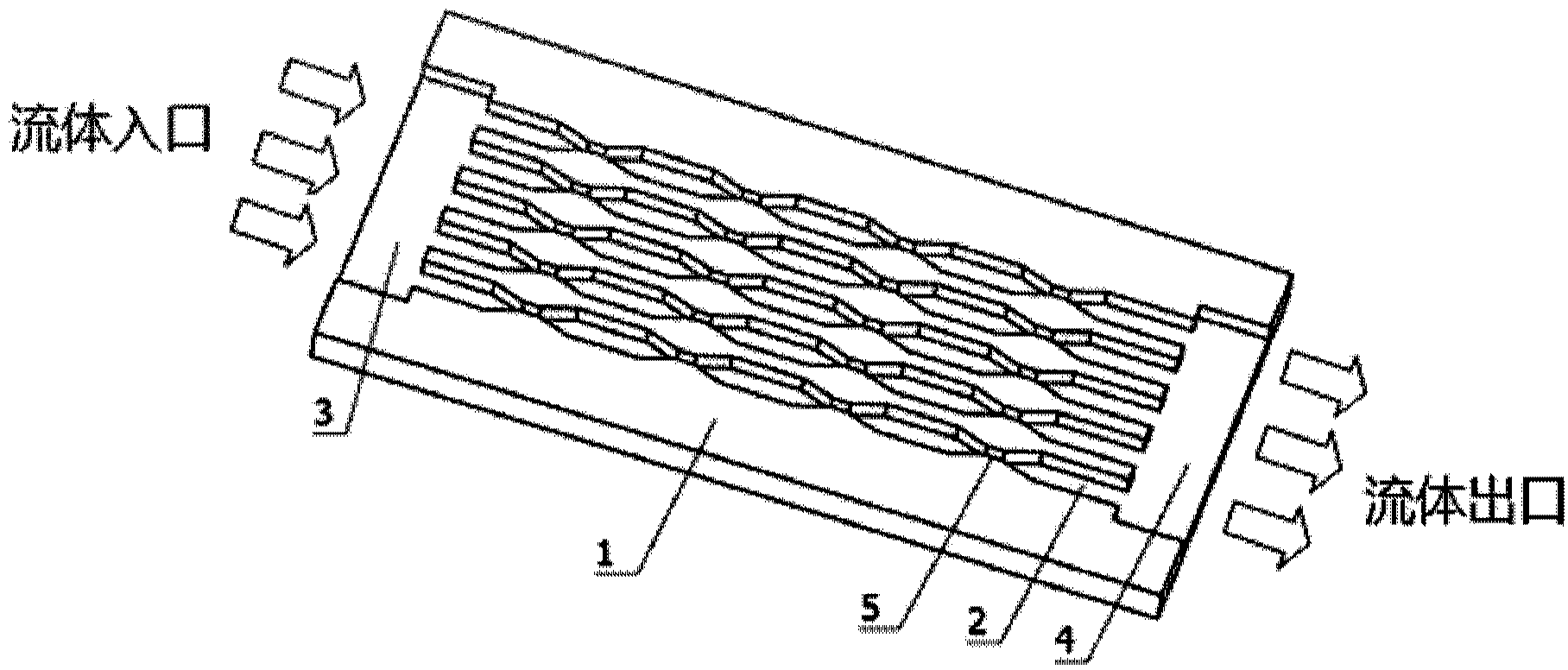
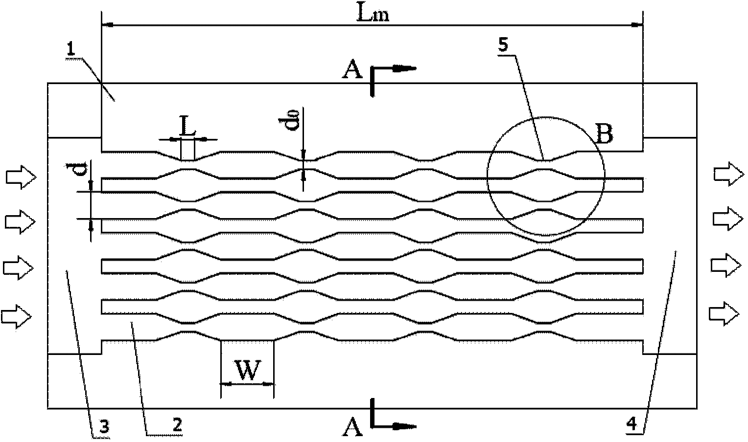
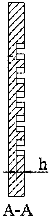
[0021] Such as figure 1 and Figure 2a , Figure 2b As shown, the low-resistance hydraulic cavitation structure for strengthening microchannel heat exchange described in the present invention includes: a base plate 1, a cooling microchannel 2, a microchannel inlet flow distribution chamber 3, a microchannel outlet liquid collection chamber 4, and an induced cavity The phenomenon of hydrodynamic structure5.

[0022] A plurality of cooling microchannels 2 are uniformly and parallelly arranged on the base plate 1. One end of the cooling microchannel is a fluid inlet, and the other end is a fluid outlet. The fluid inlet is provided with a flow distribution chamber 3, and the fluid outlet is provided with a liquid collection chamber 4. Each cooling microchannel 2 between the flow distribution chamber 3 and the liquid collection chamber 4 is provided with a tapered-divergent h...


PUM


Abstract

The invention relates to a low resistance hydraulic cavitation structure with a microchannel heat exchange enhancing function. The low resistance hydrodynamic cavitation structure mainly comprises a substrate flat plate, wherein a plurality of cooling microchannels are uniformly arranged on the substrate flat plate in parallel, and one end of each cooling microchannel is an inlet; the other end of each cooling microchannel is an outlet, and the inlet is provided with a flow distribution cavity; the outlet is provided with a liquid collection cavity, and a converging-diverging hydraulic structure for inducing a cavitation phenomenon is arranged in each cooling microchannel between the flow distribution cavity and the liquid collection cavity; the ratio of the length of the throat section of the converging-diverging hydraulic structure to the width of each cooling microchannel is 0.1 to 1, the taper angle of the inlet of the converging section of the converging-diverging hydraulic structure is 15 degrees to 45 degrees, and the taper angle of an outlet of the diverging section of the converging-diverging hydraulic structure is 15 degrees to 90 degrees. The low resistance hydraulic cavitation structure provided by the invention has the advantages of enhancing microchannel heat exchange, reducing the loss of flow resistance of liquid, and reducing the additional pump power input caused by inducing cavitation.

Description

technical field [0001] The invention belongs to the technical field of high-efficiency cooling, and in particular relates to a low-resistance hydraulic cavitation structure for strengthening microchannel heat exchange. Background technique [0002] Microchannel heat sink has become the most promising high-efficiency cooling method in the microelectronics industry due to its high-efficiency cooling capacity, simple cooling structure, and good compatibility. However, with the continuous improvement of the integration of electronic components, their power density has risen sharply. Taking high-power devices (such as IGBT) and laser diode (DL) arrays as examples, their power density has reached hundreds of watts, or even On the order of kilowatts, more than 50% of the power is consumed in the form of heat. Faced with such a high heat flux density, the cooling capacity of the traditional microchannel structure can no longer meet its cooling requirements, and there is an urgent n...

Claims


Application Information

Patent Timeline
IPC IPC(8): F28F3/04H01L23/473H01S5/024
Inventor 蔡军淮秀兰刘斌
Owner INST OF ENGINEERING THERMOPHYSICS - CHINESE ACAD OF SCI
Why Eureka
Try Eureka