
MEMS accelerometer capable of being engineered

An accelerometer, engineering technology, applied in the direction of measuring acceleration, speed/acceleration/shock measurement, measuring device, etc., can solve the problems of increased product cost, poor heat dissipation performance, large temperature coefficient, etc., to reduce the probability of errors, solve The effect of large temperature hysteresis and high detection accuracy

Active Publication Date: 2014-07-30
INST OF GEOLOGY & GEOPHYSICS CHINESE ACAD OF SCI
View PDF6 Cites 11 Cited by
  • Summary
  • Abstract
  • Description
  • Claims
  • Application Information

AI Technical Summary

Problems solved by technology

Therefore, domestic MEMS accelerometers have not been used on a large scale. The first is the accuracy problem. The current MEMS accelerometer bias and the stability of the calibration factor and the nonlinear index at full scale still have a large gap from the inertial level technical index; temperature characteristics , the current MEMS accelerometer prototypes are faced with problems such as large temperature coefficient, non-repetitive temperature characteristics, and large hysteresis. Due to the fast start-up requirements of MEMS accelerometers, they are rarely used in a constant temperature range, making temperature characteristics a constraint. One of the bottlenecks in the engineering application of accelerometers, the main factors affecting the temperature characteristics are the encapsulation and micro-assembly process of the accelerometer. Currently, the commonly used solutions are PCB board-level solutions or ceramic substrate solutions. The cost of the former is lower, but due to PCB and The material expansion coefficient of the MEMS bare chip differs by an order of magnitude, which makes its stability and temperature repeatability in the full temperature range poor. The cost of the latter ceramic substrate is high, and the material matching of the ceramic itself is closer to the accelerometer bare chip. However, its heat dissipation performance is very poor, which leads to a large temperature hysteresis in the whole accelerometer. In addition, the performance of the adhesive used for bonding is also an important factor affecting the temperature characteristics of the accelerometer; the adaptability to the mechanical environment mainly refers to the accelerometer’s resistance. Due to the electrostatic negative stiffness effect of the MEMS accelerometer, on the one hand, if the system design is not optimized enough, within the full-scale range, the instantaneous impact will appear pull-in phenomenon; Under overload, due to the unreasonable structural design, the silicon-based movable mass and the fixed plate are attracted due to the unique suction effect of the silicon-based MEMS accelerometer under large overload, and cannot be recovered during power-on
In addition, there are large changes in the zero position of the accelerometer before and after vibration and impact, which is also a problem in engineering applications; the quality consistency and cost issues are limited by the domestic MEMS processing technology, and the current MEMS accelerometer bare chip has capacity symmetry As well as problems such as poor consistency, there are currently no good solutions to many problems such as bare chip screening and testing, online debugging, etc. In order to solve the problem of online debugging, the current approach is to use bare chip pre-packaging, which avoids the impact of online debugging on Pollution of the bare chip, but the use of pre-packaging also increases the cost of the product, and is directly related to the engineering capability of the MEMS accelerometer

Method used


Image

  • MEMS accelerometer capable of being engineered
  • MEMS accelerometer capable of being engineered
  • MEMS accelerometer capable of being engineered

Examples


Embodiment Construction

[0036] Below in conjunction with accompanying drawing, the present invention is described in further detail:

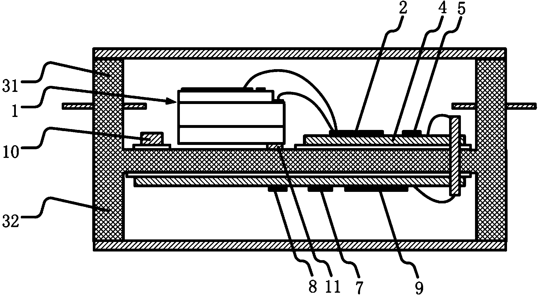
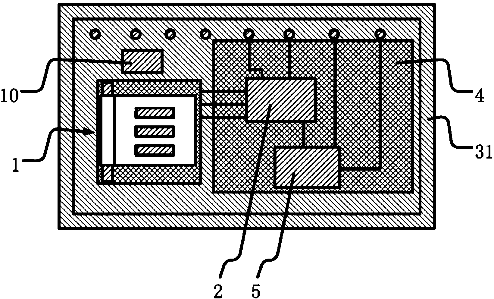
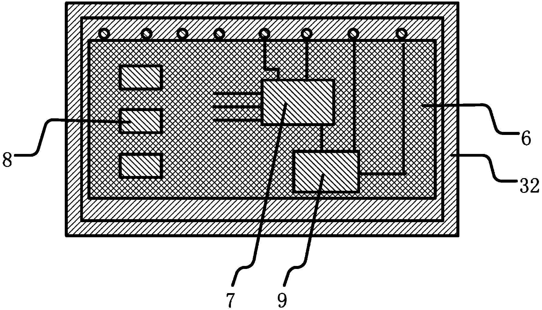
[0037] refer to figure 1 , 2 and 3, according to a kind of engineerable MEMS accelerometer provided by the present invention, comprise acceleration sensitive chip 1, signal conversion circuit, signal conditioning circuit, wherein said accelerometer also comprises temperature sensor 10, said temperature sensor 10 Close to the acceleration sensitive chip 1; the acceleration sensitive chip 1, the signal conversion circuit and the temperature sensor 10 are packaged as an independent first module, and the signal conditioning circuit is packaged as an independent second module after debugging, and the second The modules are packaged later than the first module.

[0038] Wherein, the components and circuits in the first module do not need to be debugged. Therefore, after installing the first metal shell 31, the first substrate 4, the acceleration sensitive chip 1, the sign...


PUM


Abstract

An MEMS accelerometer capable of being engineered comprises an acceleration sensitive chip, a signal conversion circuit, a first metal pipe shell, a second metal pipe shell, a first substrate, a second substrate and a signal regulating circuit. The accelerometer further comprises a temperature sensor adjacent to the acceleration sensitive chip; the acceleration sensitive chip, the signal conversion circuit and the temperature sensor are packaged into a first independent module, the signal regulating circuit is packaged into a second independent module after being debugged, and package of the second module is posterior to that of the first module. The signal conversion circuit comprises a C-V conversion circuit and a voltage reference unpacked chip; the signal regulating circuit comprises a correction and feedback circuit, a zero adjusting circuit and a filter circuit. The MEMS accelerometer solves a plurality of problems of engineering of the MEMS accelerometer and particularly the problems of temperature characteristics and environmental adaptation of impact and overload, can be used for manufacturing an acceleration sensitive element for inertia measurement and inertia navigation, and can also serve as an acceleration measurement element in the fields of bridge health monitoring and the like.

Description

technical field [0001] The invention relates to an engineerable MEMS (micro-electromechanical system) accelerometer, which belongs to the category of MEMS inertial technology, and can be used as an acceleration sensitive element for inertial measurement and inertial navigation in the fields of aviation, aerospace, weapons, etc., and can also be used as a bridge health monitor , geological exploration and other fields of acceleration measurement components. Background technique [0002] The principle prototypes of MEMS accelerometers are mostly developed in China, but they are currently facing many difficulties in engineering. Therefore, domestic MEMS accelerometers have not been used on a large scale. The first is the accuracy problem. The current MEMS accelerometer bias and the stability of the calibration factor and the nonlinear index at full scale still have a large gap from the inertial level technical index; temperature characteristics , the current MEMS accelerometer...

Claims


Application Information

Patent Timeline
Patent Type & Authority Applications(China)
IPC IPC(8): G01P15/125
Inventor 薛旭
Owner INST OF GEOLOGY & GEOPHYSICS CHINESE ACAD OF SCI
Learn More