
Waveguide array antenna high-power performance testing apparatus

A technology of waveguide array and testing device, which is applied in the field of high-power performance testing device of waveguide array antenna, and can solve problems such as low antenna, gas breakdown of antenna unit, and influence on physical experiments

Inactive Publication Date: 2014-07-30
INST OF PLASMA PHYSICS CHINESE ACAD OF SCI
View PDF5 Cites 11 Cited by
  • Summary
  • Abstract
  • Description
  • Claims
  • Application Information

AI Technical Summary

Problems solved by technology

[0003] The development of low clutter antennas at home and abroad has reached the present stage. The basic energy feeding structure of the antenna unit is built in. Several metal plates (E-plane junctions) parallel to the broad side of the waveguide distribute the microwave power to several sub-waveguides, and the sub-waveguides The array radiates microwave energy into the tokamak plasma. Since the low-clutter antenna is in the vacuum environment connected to the main vacuum chamber of the tokamak in the experiment, when the high-power microwave passes through, a large number of gas molecules adsorbed on the inner wall of the antenna unit will The release will affect the vacuum degree inside the antenna unit, and the reduction of the vacuum degree will cause gas breakdown and ignition inside the antenna unit. In addition, during the tokamak experiment, because the plasma is not a matching load, the microwave energy radiated from the antenna Can not be completely absorbed by the plasma coupling, there will be part of the microwave energy reflected from the plasma back to the antenna, this part of the reflected microwave and the incident microwave inside the antenna, superimposed in some specific areas inside the antenna unit, increasing the internal ignition of the antenna probability, and once the ignition caused by the above two reasons occurs, the reflected power will increase greatly in an instant, and even produce total power reflection. In order to protect the microwave device from being damaged by the reflected power, the control system will temporarily shut down the microwave source. , causing the microwave power not to be normally coupled into the tokamak plasma, affecting the smooth progress of physical experiments
[0004] In the past, low-power measurements were made on antennas, that is, using vector network analyzers and some non-standard measuring parts to connect with antennas to obtain antenna low-power level technical indicators, such as reflection coefficients, transmission coefficients, phases, etc., without vacuuming the antennas. For high-power performance testing in the environment, since the high-power performance of the antenna directly affects the effect of low clutter on the tokamak nuclear fusion device, it is necessary to conduct complete and accurate measurements to obtain the most realistic high-power performance of the antenna index

Method used


Image

  • Waveguide array antenna high-power performance testing apparatus
  • Waveguide array antenna high-power performance testing apparatus
  • Waveguide array antenna high-power performance testing apparatus

Examples


Embodiment Construction

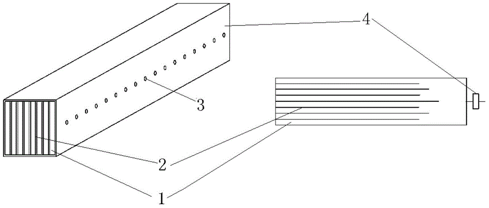
[0015] The antenna unit will emit a large amount of gas during the experiment. In order to transfer the gas molecules in the sub-waveguide to the external vacuum environment as soon as possible, a row of circular ventilation holes is generally arranged on the central axis of the wide sides of the sub-waveguide, such as figure 1 as shown, figure 1 Among them, 1 is a sub-waveguide, 2 is a sub-waveguide partition, and 3 is a vent hole. The distance between adjacent vent holes and the size of the vent holes are determined by calculation, so that the flow resistance should be minimized so that the gas molecules can be discharged from the antenna unit as soon as possible, so as to maintain a high vacuum inside the antenna unit without affecting the high Normal transmission of power microwaves.

[0016] In addition, the output end of the antenna unit is an array composed of several sub-waveguides. In order to accurately measure the high power performance of the antenna unit in a vac...


PUM


Abstract

The invention discloses a waveguide array antenna high-power performance testing apparatus. The apparatus comprises a microwave source, a circulator, a vacuum chamber, a vacuum gauge pipe, an antenna unit to be detected, a waveguide arc light detector, a ceramic window, a waveguide bent head, a directional coupler, an impedance mismatch device, a water load and the like. The microwave source outputs large-power microwaves; the circulator is used for absorbing reflection waves and protecting the microwave source; the vacuum chamber is used for establishing, maintaining and changing the vacuum degree of the environment where the antenna unit to be detected is disposed in; the vacuum gauge pipe is used for measuring the vacuum degree inside the vacuum chamber; the waveguide arc light detector is used for detecting the sparking inside the antenna unit to be detected; the ceramic window realizes gas sealing and energy transmission between the vacuum chamber and a microwave transmission line; the waveguide bent head is used for changing the spreading direction of the microwaves; the directional coupler measures the size of incident power and reflection power through performing sampling on microwave signals; the impedance mismatch device functions to manually introduce transmission mismatch and produce the reflection power with needed proportions; and the water load is used for absorbing nearly all the incident power.

Description

technical field [0001] The invention relates to the field of antenna measurement devices, in particular to a waveguide array antenna high-power performance test device. Background technique [0002] The low clutter driving current has been proved by experiments to be the most effective non-inductive driving current method on the Tokamak controlled magnetic confinement nuclear fusion device. The antenna is a very important subsystem in the low clutter system. Power Microwave energy is coupled into the tokamak plasma with a specific radiant power spectrum for heating the plasma and driving the plasma current. [0003] The development of low clutter antennas at home and abroad has reached the present stage. The basic energy feeding structure of the antenna unit is built in. Several metal plates (E-plane junctions) parallel to the broad side of the waveguide distribute the microwave power to several sub-waveguides, and the sub-waveguides The array radiates microwave energy into...

Claims


Application Information

Patent Timeline
IPC IPC(8): G01R31/00
Inventor 刘亮赵连敏刘甫坤朱文华
Owner INST OF PLASMA PHYSICS CHINESE ACAD OF SCI
Learn More