
Static threshold eliminating and dynamic threshold eliminating combined type voltage-doubler rectifier

A technology of dynamic threshold elimination and voltage doubler rectifier, which is used in output power conversion devices, conversion of AC power input to DC power output, electrical components, etc. Signal amplitude reduction and other problems to achieve the effect of reducing energy loss, achieving high-efficiency power conversion, and good impedance matching

Inactive Publication Date: 2014-07-30
FUDAN UNIV
View PDF4 Cites 18 Cited by
  • Summary
  • Abstract
  • Description
  • Claims
  • Application Information

AI Technical Summary

Problems solved by technology

[0009] 1) With the further reduction of the input RF power and the reduction of the RF signal amplitude, the circuit structure is still difficult to overcome the rectification dead zone, the conduction angle decreases, and the rectification efficiency drops rapidly;
[0010] 2) As the input RF power further decreases, the amplitude of the RF signal decreases, the on-resistance of the rectifier tube increases, and the rectifier
Traditional rectification technology often can only optimize the circuit structure and parameters under the condition of the minimum input power concerned in order to obtain efficient energy transmission under this input power. When the input power changes, the working state of the rectifier tube changes, and the equivalent input impedance changes. A large amount of power is lost due to the impedance mismatch between the antenna and the rectifier. The common relationship between power conversion efficiency and input power including impedance mismatch is as follows image 3 shown

Method used


Image

  • Static threshold eliminating and dynamic threshold eliminating combined type voltage-doubler rectifier
  • Static threshold eliminating and dynamic threshold eliminating combined type voltage-doubler rectifier
  • Static threshold eliminating and dynamic threshold eliminating combined type voltage-doubler rectifier

Examples


Embodiment

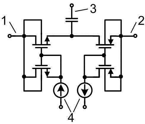
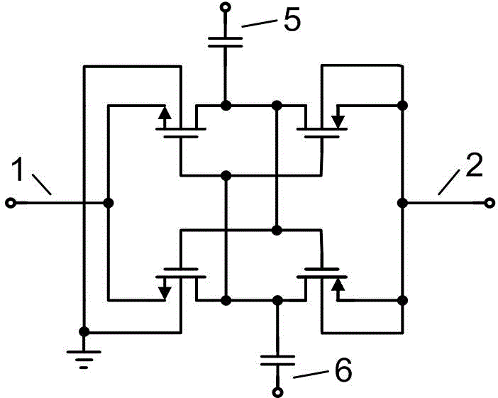
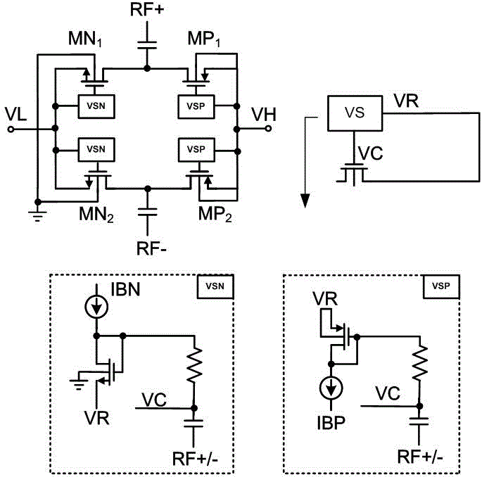
[0040] In order to describe the content of the present invention in more detail, here with Figure 5 and Figure 6 The circuit structure shown is taken as an example for explanation. Those skilled in the art know that this is just an example, not intended to limit the scope of the present invention.

[0041] Figure 5 The shown rectifier has a fully differential structure, and the single-stage rectifier unit is composed of four rectifier tubes MN1, MN2, MP1 and MP2 and corresponding four VS modules VSN and VSP, and radio frequency signals are coupled by two radio frequency capacitors. The substrate B of the NMOS rectifier tubes MN1 and MN2 is grounded, the source terminal S is connected to the DC input VL, the drain terminal D is connected to the drain terminal D of the PMOS rectifier tube, and the gate G is connected to the control signal generated by the bias module VSN of the NMOS rectifier tube. The substrate B of the PMOS rectifier tubes MP1 and MP2 is connected to the...


PUM


Abstract

The invention belongs to the technical field of energy capture, and particularly discloses a static threshold eliminating and dynamic threshold eliminating combined type voltage-doubler rectifier. According to the voltage-doubler rectifier, the static threshold eliminating technology and the dynamic threshold eliminating technology are combined, the equivalent threshold of a rectifier tube is changed through direct current bias so as to increase the positive-direction breakover current of the rectifier tube, and the rectifier tube is switched off with anti-phase radio-frequency signals so as to reduce the reverse leakage current of the rectifier tube. According to the voltage-doubler rectifier, high-efficiency power conversion under ultralow radio-frequency power input can be realized, good impedance matching within the bandwidth of wide input power can be realized, and then energy transmission efficiency within a wide power band is improved. When the voltage-doubler rectifier is applied to the fields such as radio frequency identification (RFID), label reading and writing sensitivity can be improved greatly, and then system sensitivity is improved.

Description

technical field [0001] The invention belongs to the technical field of energy acquisition, and specifically relates to a converter from AC power to DC power, also known as a voltage doubler rectifier. Background technique [0002] Wireless energy transmission and acquisition technology is widely used in many fields. The usual mode is that the antenna induces an AC voltage signal, and then converts the AC power to DC power through a rectifier or a voltage doubler rectifier. [0003] With the development of technologies such as radio frequency identification (RFID), the power conversion efficiency of wireless energy transfer becomes more and more important. In some applications, such as the long-distance working mode of UHF RFID, people hope to realize high-efficiency power conversion under ultra-low RF power (such as -20dBm or less) input. To improve power conversion efficiency, it is necessary to increase the forward conduction current and reduce the reverse leakage current...

Claims


Application Information

Patent Timeline
IPC IPC(8): H02M7/217
Inventor 陈勇闵昊闫娜谈熙
Owner FUDAN UNIV
Learn More