
Time-digital converter, full-digital phase-locked loop circuit and method

A time-to-digital conversion, all-digital phase-locked loop technology, applied in the electrical field, can solve the problems of increasing the circuit scale, multi-delay units, etc.

Active Publication Date: 2014-07-30
HUAWEI TECH CO LTD
View PDF2 Cites 18 Cited by
  • Summary
  • Abstract
  • Description
  • Claims
  • Application Information

AI Technical Summary

Problems solved by technology

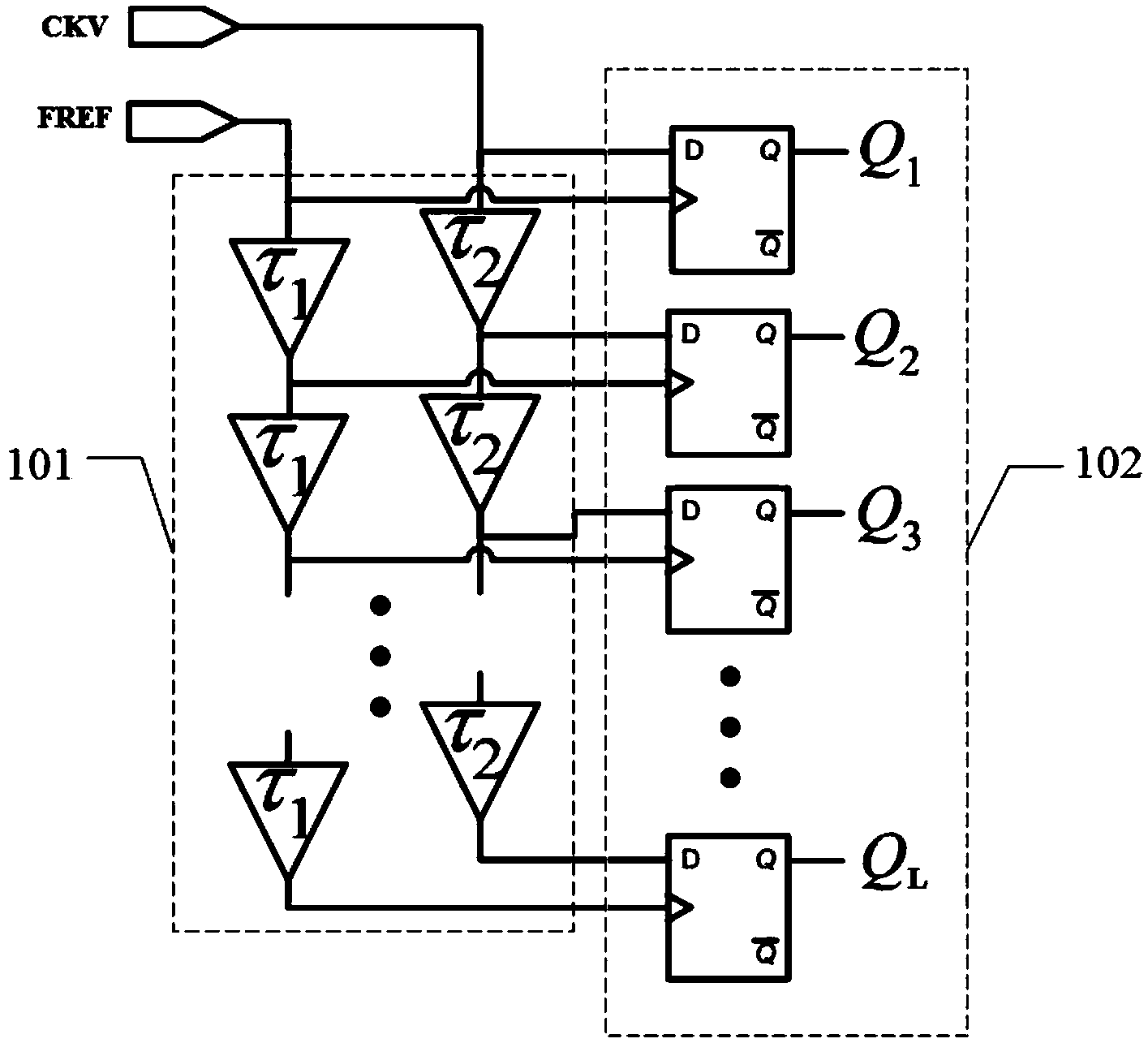
Therefore, the problem existing in the prior art is: when the measurement time difference between the FREF signal and the CKV signal is large, in order to ensure a certain time accuracy, more delay units are required, which increases the circuit scale

Method used


Image

  • Time-digital converter, full-digital phase-locked loop circuit and method
  • Time-digital converter, full-digital phase-locked loop circuit and method
  • Time-digital converter, full-digital phase-locked loop circuit and method

Examples


Embodiment Construction

[0063] The following examples are given to describe the present invention.

[0064] Such as figure 2 As shown, the embodiment of the present invention provides a time-to-digital converter, which can be applied to an all-digital phase-locked loop circuit, which includes: a phase interpolation circuit 201 and a time-to-digital converter connected to the phase interpolation circuit 201 conversion circuit 202 .

[0065] The phase interpolation circuit 201 is used for receiving a first reference clock signal and a second reference clock signal, the phase of the first reference clock signal is ahead of the phase of the second reference clock signal, and the phase of the first reference clock signal is signal and the second reference clock signal to perform phase interpolation to generate a third reference clock signal, and output the third reference clock signal to the time-to-digital conversion circuit 202 .

[0066] The time-to-digital conversion circuit 202 is configured to re...


PUM


Abstract

The invention discloses a time-digital converter. The time-digital converter comprises a phase interpolation circuit and a time-digital conversion circuit, wherein the phase interpolation circuit is used for receiving a first reference clock signal and a second reference clock signal, performing phase interpolation on the first reference clock signal and the second reference clock signal to generate a third reference clock signal and outputting the third reference clock signal to the time-digital conversion circuit; the time-digital conversion circuit is used for receiving the third reference clock signal and a fourth clock signal, measuring the phase difference between the third reference clock signal and the fourth clock signal and converting the measured phase difference into a digital signal to be output, wherein the phase difference between the third reference clock signal and the fourth clock signal is smaller than that between the first reference clock signal and the fourth clock signal. According to the time-digital converter, while time accuracy is ensured, the number of delay units in use in the time-digital conversion circuit can be reduced.

Description

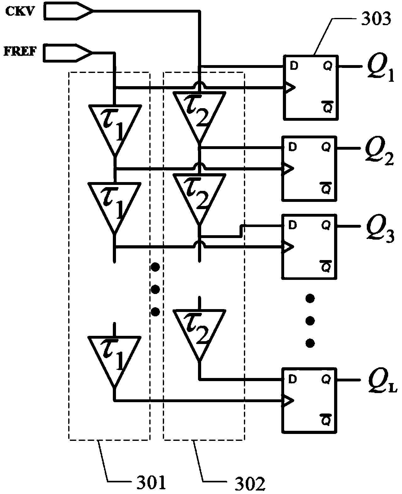
technical field [0001] The invention relates to the field of electricity, in particular to a time-to-digital converter, an all-digital phase-locked loop circuit and a method. Background technique [0002] The time-to-digital converter is mainly used in an all-digital phase-locked loop circuit. Its function is to measure the phase difference between two clock signals and convert the phase difference into a digital signal. Such as figure 1 As shown, the time-to-digital converter includes a delay circuit 101 and a decision circuit 102. The delay circuit 101 is used to input two clock signals, which are respectively an external reference clock signal FREF and a feedback clock signal CKV, and to perform the two clock signals Delayed and triggered by the flip-flop in the decision circuit 102, the quantized time interval between the two clock signals is obtained. Wherein, delay circuit 101 can be made up of vernier delay chain, and vernier delay chain comprises first delay chain ...

Claims


Application Information

Patent Timeline
IPC IPC(8): H03L7/085H03L7/08
CPCG04F10/005H03L7/085H04L7/0331H04L7/0025
Inventor 周盛华李晓宇
Owner HUAWEI TECH CO LTD
Learn More