Electronic helical accelerator

An accelerator and helical technology, applied in the field of electron helical accelerators, can solve the problems of low beam power and can not meet the needs of material irradiation, and achieve the effect of reducing the space occupied, high radio frequency utilization efficiency, and good use economy.

Active Publication Date: 2014-07-30
CHINA INSTITUTE OF ATOMIC ENERGY
View PDF9 Cites 7 Cited by
  • Summary
  • Abstract
  • Description
  • Claims
  • Application Information

AI Technical Summary

Problems solved by technology

[0008] In order to solve the problem that the average beam current power of the existing electron accelerator is low and cannot meet the use requirements in the field of material irradiation, and at the same time take into account the economical use, the invention provides an electron helical accelerator

Method used


Image

  • Electronic helical accelerator
  • Electronic helical accelerator

Examples


Embodiment 1

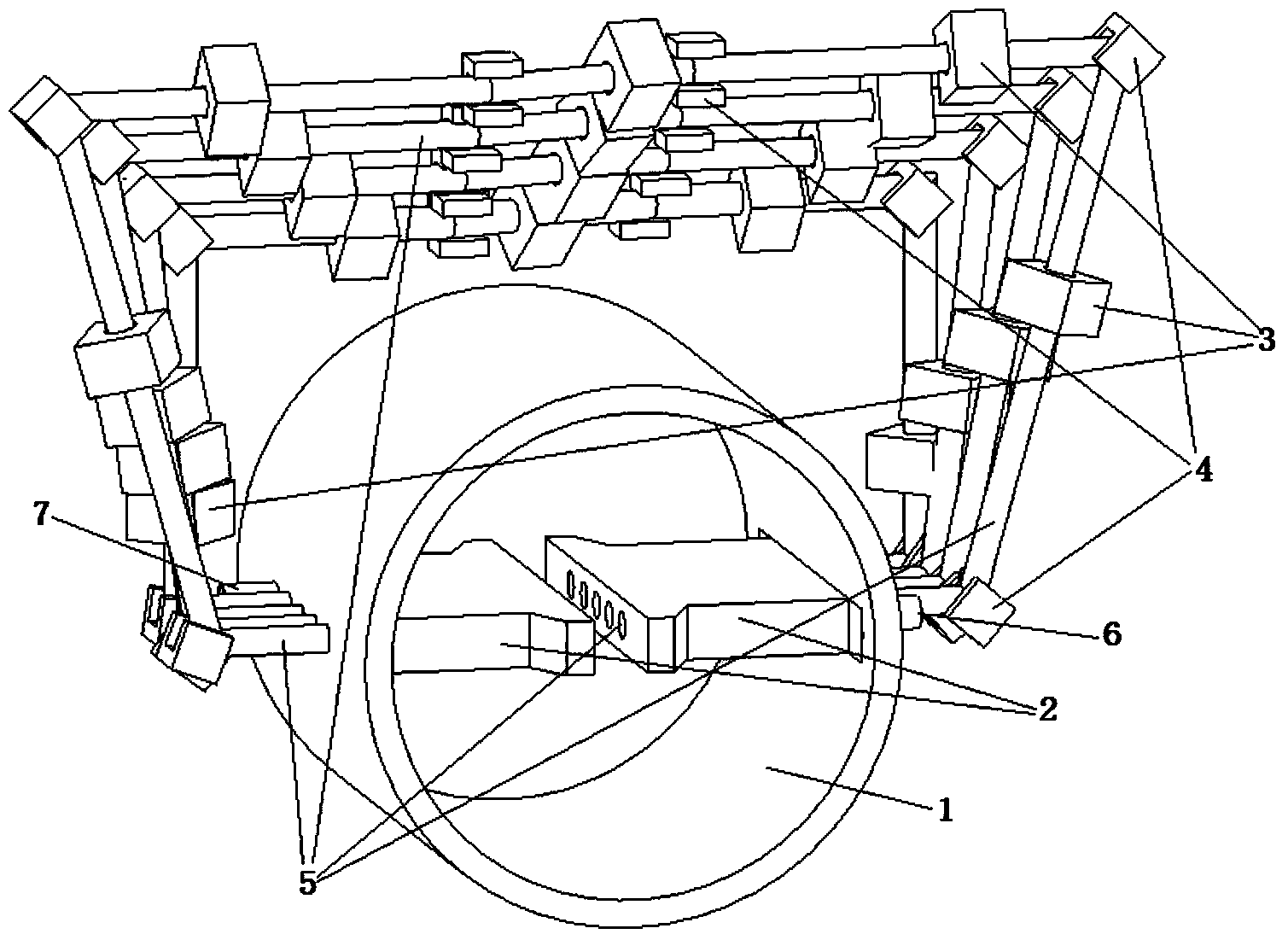
[0023] An electron spiral accelerator, such as figure 1 As shown, the electron spiral accelerator includes a radio frequency resonant cavity 1, a pair of ridge electrodes 2, a quadrupole magnet 3, a deflection magnet 4, a beam movement channel 5, a channel entrance 6, and a channel exit 7. The working frequency band of its radio frequency power source is is 100MHz, and the shape of the radio frequency resonant cavity 1 is a cylindrical cavity;

[0024] The electron spiral accelerator also includes a gate-controlled electron gun, the grid voltage waveform of which is a sine wave, and the working frequency is the same as that of the radio frequency power source;

[0025] The beam movement tunnel 5 includes a beam deflection tunnel and a ridge electrode beam tunnel. The beam deflection tunnel passes through the radio frequency resonant cavity 1 housing and communicates with the ridge electrode beam tunnel. The spatial structure of the beam movement tunnel 5 It is a spring-type t...

Embodiment 2

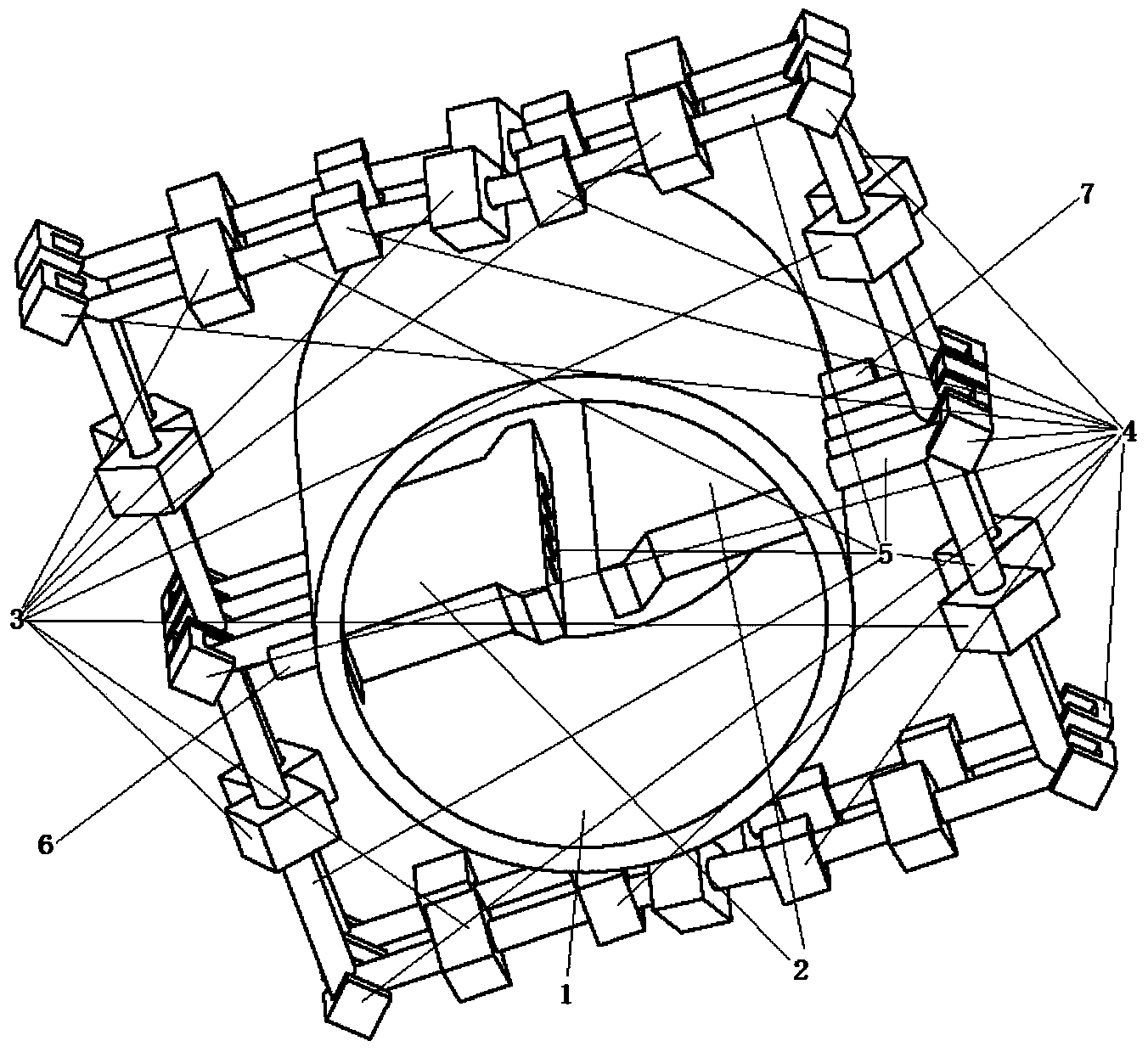
[0029] An electron spiral accelerator, such as figure 2 As shown, the electron spiral accelerator includes a radio frequency resonant cavity 1, a pair of ridge electrodes 2, a quadrupole magnet 3, a deflection magnet 4, a beam movement channel 5, a channel entrance 6, and a channel exit 7. The working frequency band of its radio frequency power source is is 100MHz, and the shape of the radio frequency resonant cavity 1 is a cylindrical cavity;

[0030] The electron spiral accelerator also includes a gate-controlled electron gun, the grid voltage waveform of which is a sine wave, and the working frequency is the same as that of the radio frequency power source;

[0031] The beam movement tunnel 5 includes a beam deflection tunnel and a ridge electrode beam tunnel. The beam deflection tunnel passes through the radio frequency resonant cavity 1 housing and communicates with the ridge electrode beam tunnel. The spatial structure of the beam movement tunnel 5 It is an 8-shaped th...


PUM


Abstract

The invention relates to an accelerator, aims at solving the problem that an existing electronic accelerator is low in average beam current power and cannot meet the using demand of the fields of material irradiation and the like, meanwhile gives consideration to using economical efficiency and provides an electronic helical accelerator. The electronic helical accelerator comprises a radio-frequency resonance cavity, a pair of ridge-shaped electrodes, a four-pole magnet, a deflection magnet, a beam current motion pore passage, a pore passage inlet, a pore passage outlet and a grid-control electronic gun, wherein the beam current motion pore passage comprises a beam current deflection pore passage and ridge-shaped electrode beam current pore passages, the four-pole magnet and the deflection magnet are arranged outside the beam current deflection pore passage, electronic beams led from the pore passage inlet is subjected to acceleration, focusing and deflection in the beam current motion pore passage and finally jet out of the pore passage outlet, and the whole acceleration process is finished. The electronic helical accelerator is high in radio-frequency utilization efficiency and good in using economical efficiency, effectively improves the average beam current power and can well meet the using demand of the fields of material irradiation and the like.

Description

technical field [0001] The invention relates to an accelerator, in particular to an electron spiral accelerator. Background technique [0002] Electron accelerator is a commonly used accelerator, which is widely used in scientific research, medical treatment, non-destructive testing and material irradiation and other fields. There are many types of electron accelerators, including electrostatic high-voltage accelerators, electron linear accelerators, and electron induction accelerators. Among them, high-power electron accelerators for material irradiation mainly use electron linear accelerators, such as commonly used S-band irradiation accelerators, and the beam parameters of the main models are 10MeV / 20kW. Restricted by the utilization efficiency of radio frequency and the power source of radio frequency, the beam power of the electron linear accelerator is difficult to break through 30kW. [0003] However, in order to meet the practical needs of increasing beam power req...

Claims


Application Information

Patent Timeline
Patent Type & Authority Applications(China)
IPC IPC(8): H05H13/10
Inventor 李金海李春光杨京鹤
Owner CHINA INSTITUTE OF ATOMIC ENERGY
Why Eureka
Try Eureka