
Vibrating plate, liquid jetting device and printing device

A vibrating plate and nozzle technology, which is applied in printing and other directions, can solve the problems of film layer detachment, zirconia layer detachment, long annealing time, etc., and achieve the effect of not being easily warped and deformed, and preventing the reduction of displacement change

Active Publication Date: 2014-08-06
ZHUHAI SAILNER 3D TECH CO LTD
View PDF10 Cites 3 Cited by
  • Summary
  • Abstract
  • Description
  • Claims
  • Application Information

AI Technical Summary

Problems solved by technology

[0004] However, the generation temperature of the zirconium dioxide layer in the existing vibrating plate is relatively high and the annealing time is long, and the zirconium layer is subjected to thermal oxidation to generate greater stress, which causes cracks to appear on the zirconium dioxide layer, and the zirconium dioxide layer The zirconium dioxide layer falls off after cooling due to the deformation of the vibration plate and the pressure chamber due to the release of thermal stress
On the other hand, in the prior art, the silicon substrate is easily warped and deformed during the cooling process after being heated at a high temperature, which leads to the detachment of the thin film layer of the adjacent vibrating plate.

Method used


Image

  • Vibrating plate, liquid jetting device and printing device
  • Vibrating plate, liquid jetting device and printing device
  • Vibrating plate, liquid jetting device and printing device

Examples


Embodiment Construction

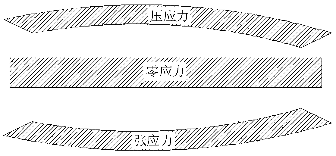
[0040] figure 1 It is a schematic diagram of the deformation of the vibrating plate when it is subjected to compressive stress or tensile stress or the stress is zero. Such as figure 1 As shown, when the internal stress of the vibrating plate is tensile stress, the vibrating plate will be subjected to the action of tensile stress, which will cause the two ends of the vibrating plate to be higher than the middle part of the warping deformation. When the internal stress of the vibrating plate is zero, the vibrating plate is in the In a naturally flat state, when the internal stress of the vibrating plate is compressive, the vibrating plate will be subjected to compressive stress, which will cause the middle part of the vibrating plate to be higher than the two ends of the warping deformation.

[0041] In the existing process of manufacturing nozzles, high-temperature oxidation or high-temperature calcination and annealing processes are required, and at the same time, due to the...


PUM

PropertyMeasurementUnit
Thicknessaaaaaaaaaa

Abstract

The embodiment of the invention provides a vibrating plate, a liquid jetting device and a printing device. The vibrating plate comprises a silicon dioxide layer and a silicon nitride layer, wherein the silicon nitride layer is arranged on the silicon dioxide layer, the stress of the silicon dioxide layer and the stress of the silicon nitride layer are counteracted so that the stress resultant of the vibrating plate can be zero, the vibrating plate is not prone to being cocked and deformed, and meanwhile the displacement variation of a piezoelectric element in the process that the piezoelectric element is repeatedly driven can be prevented from being reduced.

Description

technical field [0001] Embodiments of the present invention relate to liquid ejection head manufacturing technology, in particular to a vibrating plate, liquid ejection device and printing equipment. Background technique [0002] In the prior art, a piezoelectric element is provided on the vibration plate of the liquid ejection head, and a voltage is applied to the piezoelectric element to deform or vibrate the vibration plate, so that the liquid ejection head in the printing device ejects ink droplets. Among them, piezoelectric elements generally use lead-containing piezoelectric materials, and lead in piezoelectric elements is easy to diffuse into the silicon dioxide layer as a vibration plate, reducing the melting point of the silicon dioxide layer. Therefore, on the silicon dioxide layer When firing piezoelectric materials, the silicon dioxide layer is easily melted by heat. [0003] In the prior art, by first setting a zirconium dioxide layer on the silicon dioxide lay...

Claims


Application Information

Patent Timeline
IPC IPC(8): B41J2/14
Inventor 陈晓坤佟鑫
Owner ZHUHAI SAILNER 3D TECH CO LTD
Learn More